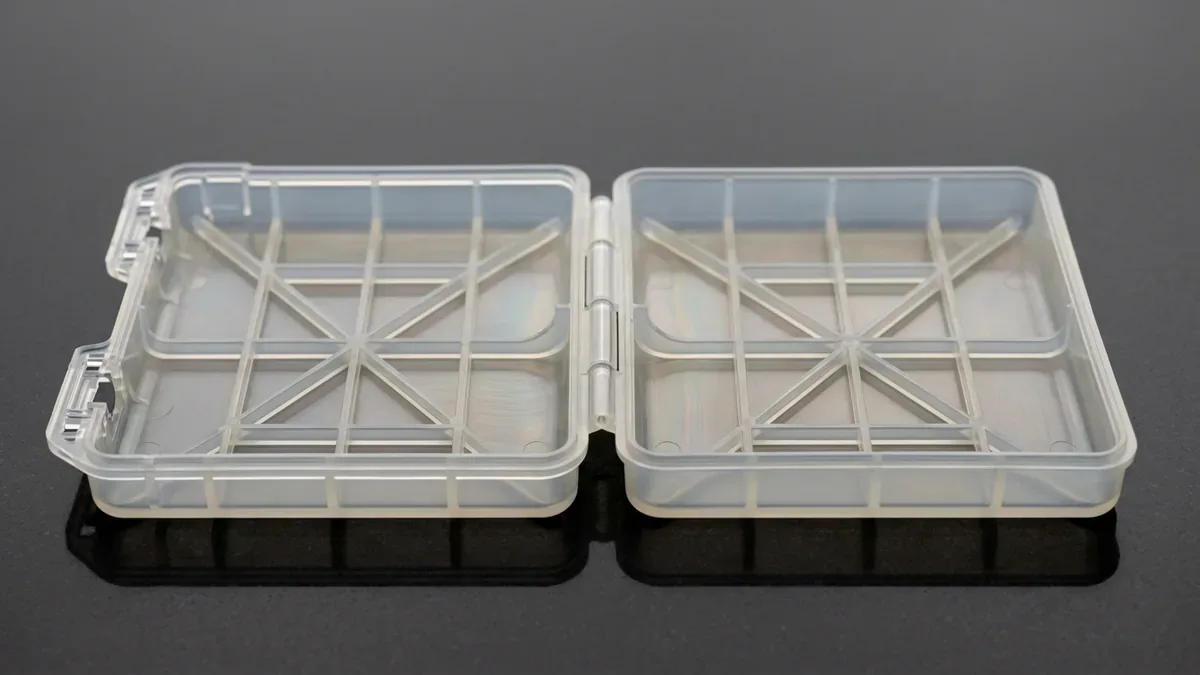
Designing plastic enclosures with integrated moving mechanisms requires intelligent part consolidation. Therefore, executing an optimal living hinges design eliminates separate metal pins, fasteners, and secondary assembly steps. A living hinge bridges two rigid plastic bodies using a thin, flexible polymer web. Consequently, production costs fall significantly while mechanical reliability increases.
However, successful living hinges demand rigorous material selection and precise cross-sectional geometry. Improperly dimensioned hinges tear or fatigue prematurely after only a few flex cycles. In this engineering guide, we examine fundamental design rules for living hinges. Furthermore, we contrast high-volume injection molding against rapid 3D printing prototyping methods.
1. Cross-Sectional Geometry and Coining DFM Rules
The cross-sectional profile of a living hinge directly dictates its mechanical fatigue resistance. Typically, a molded hinge web thickness ranges between 0.25 mm and 0.50 mm. If the web is too thick, excessive bending strain induces permanent plastic deformation. Conversely, excessively thin webs freeze off prematurely during mold injection filling.
Engineers specify generous transition radii where the thin web blends into surrounding thick walls. Sharp corners create localized stress concentrations that initiate tearing during opening cycles. In addition, post-mold mechanical coining compresses polymer chains while hot. Moreover, coining stretches molecular polymer chains along the bending axis. Consequently, this operation increases flex life from hundreds to millions of cycles.
2. Material Selection: Polypropylene, Polyethylene, and Engineering Resins
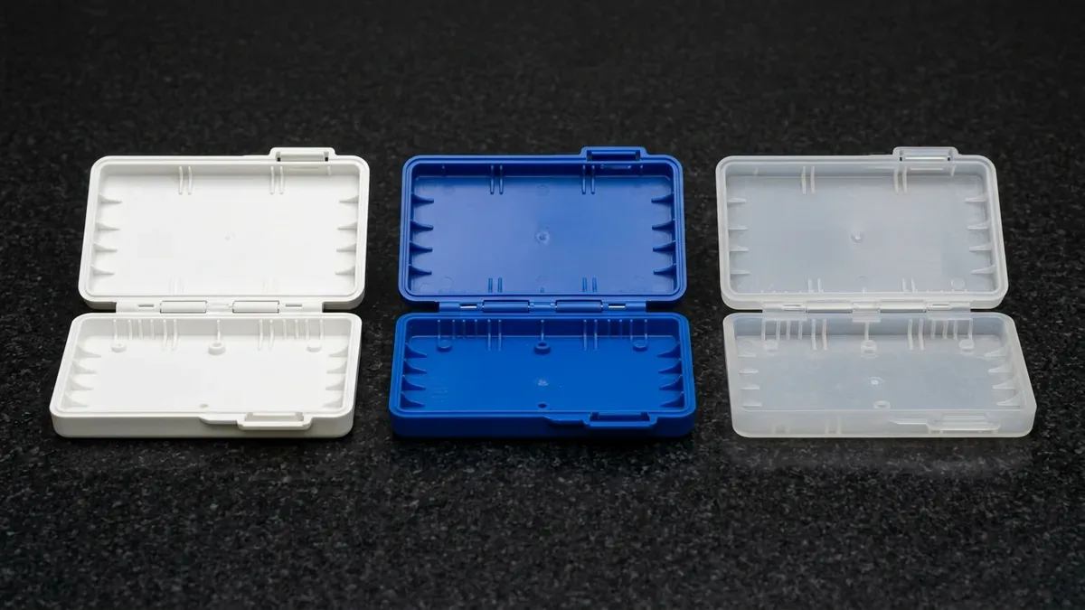
Material choice represents the single most important factor determining living hinge survivability. Polypropylene serves as the undisputed industry standard resin for flexural living hinges. Specifically, polypropylene features a unique molecular structure that orients under tensile bending stress. Consequently, repeated flexure actually work-hardens the hinge section rather than causing brittle micro-cracking.
High-density polyethylene offers reasonable flexibility for basic container closures and shampoo caps. However, polyethylene exhibits lower tensile yield strength and higher creep tendency under sustained loads. For high-temperature automotive applications, thermoplastic vulcanizates and specialized polyamides provide robust alternatives. Through our custom injection molding services, tooling specialists optimize gate locations. Thus, molten resin flows perpendicularly across the hinge section without hesitation.
The comparative engineering characteristics of living hinge manufacturing processes are outlined in the table below.
| Manufacturing Technology | Compatible Resin Systems | Hinge Web Thickness Range | Typical Flex Fatigue Life |
|---|---|---|---|
| High-Pressure Injection Molding | PP, PE, TPE, Polyurethane | 0.25 mm to 0.50 mm | Over 1,000,000 cycles |
| Selective Laser Sintering (SLS) | PA12, Flexible TPU Powders | 0.60 mm to 1.20 mm | 1,000 to 10,000 cycles |
| Multi Jet Fusion (MJF) | Polyamide PA11 / PA12 | 0.50 mm to 1.00 mm | 5,000 to 20,000 cycles |
| Vacuum Polyurethane Casting | Elastomeric Flexible Polyurethanes | 0.80 mm to 1.50 mm | 500 to 2,000 cycles |
| FFF / FDM 3D Printing | PP Filaments, Nylon Composites | 0.80 mm to 1.50 mm | 100 to 500 cycles |
3. 3D Printing Functional Living Hinges for Prototyping
Prototyping living hinges using additive manufacturing historically posed major engineering challenges. Standard photopolymer SLA resins remain too brittle to withstand sharp 180-degree bending radii. However, modern powder bed fusion technologies have transformed functional prototype validation. Specifically, SLS nylon 3D printing utilizes ductile PA12 and PA11 powders effectively.
To print a functional hinge, engineers increase the web thickness to approximately 0.8 mm. Furthermore, parts must orient parallel to the recoater blade on the build platform. This strategic orientation prevents delamination between successive laser-sintered powder layers. In addition, flame treating or warm annealing printed hinges enhances molecular chain ductility significantly before functional cycle testing.
4. Tooling Gating Strategy and Mold Flow Analysis
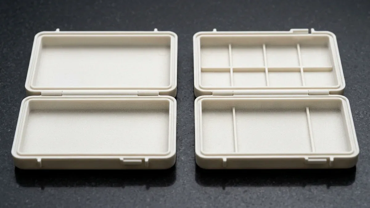
Injection mold tooling design dictates the ultimate molecular alignment within the living hinge web. Mold flow analysis ensures the melt front completely crosses the thin hinge restriction uniformly. Gate locations must place injection nozzles on one side of the hinge. Consequently, molten resin flows continuously across the hinge without forming hazardous weld lines.
If melt fronts meet inside the thin hinge section, a cold weld line forms instantly. Weld lines slash flex fatigue endurance by up to ninety percent, causing immediate hinge separation. Furthermore, high-pressure injection parameters ensure full packing before gate freeze occurs. Therefore, AS Prototypes performs rigorous mold flow simulations on every production tool before cutting hardened mold steel cavities.
The mechanical properties and application envelopes of primary living hinge polymers are compared below.
| Polymer Material | Flexural Modulus (GPa) | Notched Izod Impact (kJ/m²) | Core Application Sector |
|---|---|---|---|
| Polypropylene Homopolymer | 1.40 to 1.70 | 2.5 to 4.0 | Chemical dispensing caps and clamshell packaging. |
| Polypropylene Impact Copolymer | 1.10 to 1.30 | 8.0 to 15.0 | Automotive fuse boxes and electrical junction covers. |
| High-Density Polyethylene (HDPE) | 0.80 to 1.20 | 4.0 to 9.0 | Consumer bottle closures and snap caps. |
| SLS Polyamide 12 (Nylon) | 1.50 to 1.80 | 4.5 to 6.0 | Functional verification prototypes and electronics clips. |
| Thermoplastic Elastomer (TPE) | 0.05 to 0.20 | No break | Medical device port valves and wearable gaskets. |
5. Technical Engineering FAQ
The ideal web thickness ranges from 0.25 mm to 0.50 mm with a minimum transition radius of 0.75 mm. This balance prevents high injection filling pressures while keeping bending strains within elastic limits.
Polypropylene molecules orient along the direction of flow and tensile stress. When bent while hot, crystalline chains align, yielding exceptional fatigue resistance exceeding millions of flex cycles without breaking.
Yes. Selective laser sintering using PA12 or PA11 powders produces functional living hinges. Hinge webs must be designed slightly thicker than molded counterparts to ensure sufficient interlayer bonding strength.
Transition Seamlessly from Rapid Tooling to High-Precision Molding
Optimize cavity life, gate geometry, and part unit economics with our in-house tooling and injection molding engineering team. Upload your 3D CAD models (STEP/IGES) for a comprehensive Moldflow and DFM manufacturability assessment.
Upload 3D CAD for Tooling & Molding DFM Review