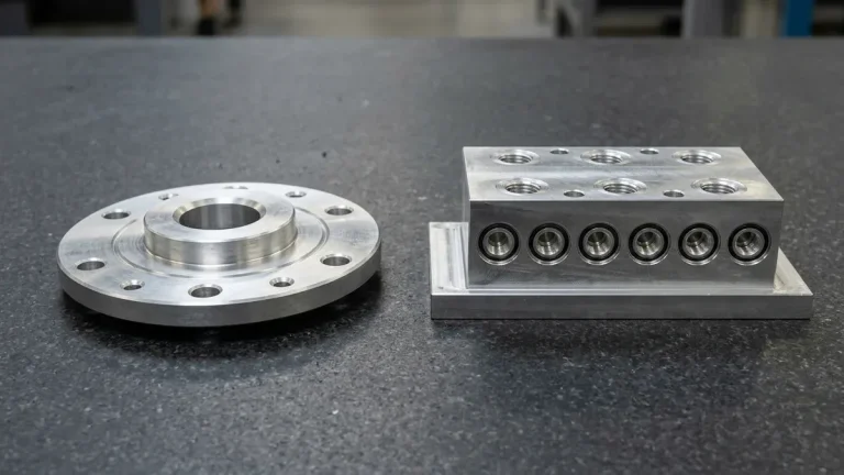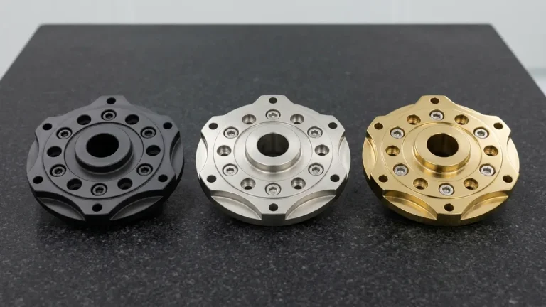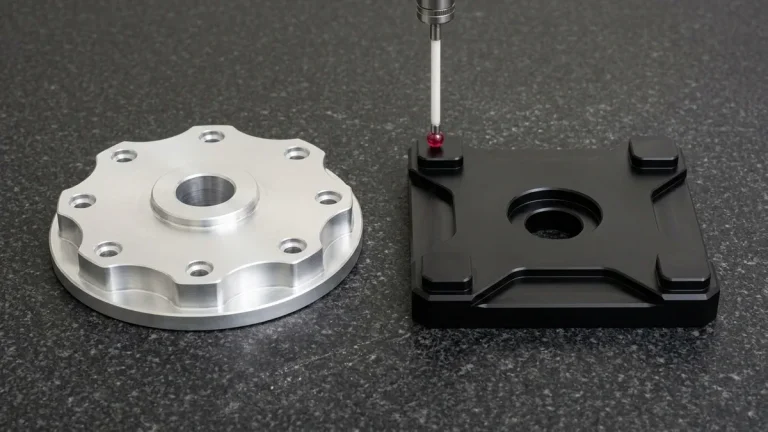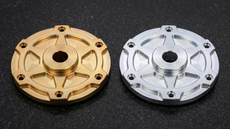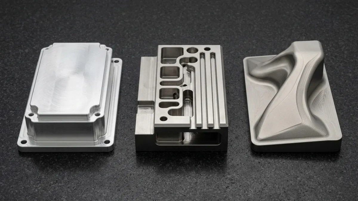
Across modern precision manufacturing, CNC milling serves as the foundational subtractive methodology for transforming raw metallic billets and engineering polymer stock into complex, mission-critical components. From monolithic 5-axis aerospace airframe bulkheads to micro-fluidic diagnostic manifolds and optical mold cores, milling operations dictate the dimensional fidelity, surface integrity, and geometric tolerances of modern hardware.
However, “milling” is far from a monolithic process. Selecting among the diverse types of milling operations requires a deep understanding of cutting kinematics, chip-thinning dynamics, tool engagement vectors, and machine tool rigidity. Choosing an inappropriate milling technique—such as deploying conventional up-milling on work-hardening stainless steels or utilizing standard slotting toolpaths in deep cavities—triggers severe tool deflection, rapid abrasive edge wear, chatter vibrations, and costly part scrapping.
At AS Prototypes, with over a decade of advanced rapid prototyping and production CNC machining expertise, our facility operates high-speed 3-axis, 4-axis, and continuous 5-axis machining centers. This comprehensive engineering guide breaks down the core classifications of CNC milling operations, contrasts climb vs. conventional cutting mechanics, details advanced high-efficiency strategies like trochoidal and high-feed milling, and provides an alloy-by-alloy operational benchmark matrix to help engineering teams optimize their components for manufacturability and cost efficiency.
- 1. The Fundamental Kinematics of Milling: Cutting Vectors & Chip Formation
- 2. Climb Milling vs. Conventional Milling: The Mechanics of Chip Thickness
- 3. Core Classifications of Precision Milling Operations
- 4. Engineering Comparison Matrix: Selecting the Optimal Milling Operation
- 5. Design for Manufacturability (DFM): Milling-Conscious Modeling Guidelines
- 6. Technical Engineering FAQ
1. The Fundamental Kinematics of Milling: Cutting Vectors & Chip Formation
In subtractive CNC machining, milling is fundamentally defined by an interrupted cutting process: a multi-toothed rotating cutting tool removes material as it traverses relative to a stationary or linearly fed workpiece. The geometric relationship between the tool’s axis of rotation and the feed vector establishes two broad mechanical classifications:
- Face Milling (Perpendicular Orientation): The cutter’s rotational axis is positioned perpendicular to the generated surface. Material removal occurs predominantly along the face and corner radius of the tool inserts, with peripheral cutting edges generating the outer boundary. Face milling prioritizes surface flatness, high material removal rates (MRR), and fine surface roughness (Ra).
- Peripheral Milling / Slab Milling (Parallel Orientation): The cutter’s rotational axis is parallel to the generated surface. Cutting occurs entirely along the outer cylindrical periphery of the tool. Common variants include shoulder milling, deep contour profiling, and slotting. Peripheral milling induces bending moments along the tool shank, demanding careful management of radial cutting loads to prevent tool deflection.
2. Climb Milling vs. Conventional Milling: The Mechanics of Chip Thickness
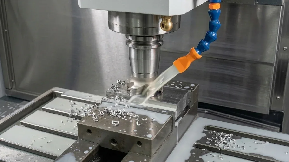
Every machinist and CAM programmer must choose between two engagement directions: climb milling (down milling) and conventional milling (up milling). This choice governs tool life, cutting temperature, and surface quality.
| Kinematic Attribute | Climb Milling (Down Milling) | Conventional Milling (Up Milling) |
|---|---|---|
| Feed Direction vs. Rotation | Workpiece feeds in the same direction as cutter tooth rotation. | Workpiece feeds against the direction of cutter tooth rotation. |
| Chip Thickness Profile | Starts at maximum (hmax = fz) and tapers to zero at tooth exit. | Starts at zero and increases to maximum at tooth exit. |
| Initial Tooth Engagement | Instantaneous shearing cut into clean virgin material; zero initial rubbing. | Initial rubbing and plowing until chip thickness exceeds hmin, causing burnishing. |
| Cutting Force Vector | Downward vertical force presses workpiece firmly into fixture/table. | Upward vertical force lifts workpiece away from fixture bed, promoting vibration. |
| Work Hardening Propensity | Minimal; heat is evacuated inside the thick portion of the chip. | Severe; friction plowing strain-hardens stainless steel, titanium, and Inconel. |
| Modern Recommendation | Standard protocol on all modern preloaded ball-screw CNC machines. | Reserved for legacy manual mills with backlash, or cutting abrasive casting scale. |
The AS Prototypes Machining Rule: We mandate climb milling across 98% of CNC operations. Because the cutter tooth engages at maximum thickness, the tool bites immediately into fresh material without burnishing or work-hardening. The resulting downward force stabilizes the workpiece against the fixture jaws, improving tool life by 2 × to 3 × and generating mirror-grade finishes (Ra ≤ 0.4 μm).
3. Core Classifications of Precision Milling Operations
1. Face Milling & Wiper Technology
Face milling is deployed to generate large planar reference datums. Large indexable face mills (ranging from Ø 40 mm to Ø 160 mm) mount multiple carbide, cermet, or PCD inserts at positive axial and radial rake angles.
- Cutter Engagement Ratio: For maximum process stability and minimal vibration, the cutter diameter (Dc) should ideally span 1.2 × to 1.5 × the workpiece width (w), positioned with an offset center to ensure smooth tool entry.
- Wiper Inserts: By replacing one standard insert with a specialized “wiper” insert possessing a micro-flat edge geometry, machinists can double feed rates (fz) while simultaneously improving surface finish from Ra 1.6 μm down to Ra 0.2 μm, eliminating secondary surface grinding.
2. 90° Shoulder & End Milling
Shoulder milling generates simultaneous 90-degree vertical side walls and flat bottom floors. Solid micro-grain carbide endmills or 90° indexable shoulder cutters ensure clean transitions without leaving steps or undercuts between depth passes. This process is essential for milling precision bearing pockets, seal gland recesses, and structural rib networks.
3. High-Feed Milling (HFM)
High-Feed Milling is an aggressive roughing technique that exploits extreme chip thinning. HFM cutters feature small lead angles (10° to 20°) and shallow axial depths of cut (ap ≈ 0.5 to 1.5 mm).
Because the thin chip allows dramatic increases in feed per tooth (fz ≥ 1.0 to 2.5 mm/tooth), MRR increases exponentially. Crucially, the shallow lead angle directs cutting forces axially straight up into the rigid machine spindle rather than radially into the tool shank, eliminating cutter deflection on deep cavities.
4. Dynamic & Trochoidal Adaptive Milling
Traditional CAM offset pocketing drives cutters into sharp corners, spiking the tool radial engagement angle (θe) from 30° to 180°, causing instantaneous chatter, tool deflection, and thermal shock. Modern adaptive trochoidal milling programs smooth, continuous circular toolpaths maintaining a constant engagement angle (typically θe ≤ 35°–45°).
This allows full-depth axial engagement (ap = 2 × to 3 × Dc) paired with light radial step-overs (ae = 5% to 15% Dc), distributing heat evenly across the entire flute length rather than concentrating wear at the tool tip. This is the gold standard for roughing titanium alloys (Ti-6Al-4V) and heat-resistant stainless steels (17-4PH, 316L).
5. Precision Thread Milling vs. Tapping
While traditional tapping utilizes a single axial tool that matches the hole thread pitch, thread milling deploys a rotating helical toolpath (G02/G03 with simultaneous Z feed):
- Zero Tool Breakage Scrap: If a tap breaks inside a high-value 5-axis aerospace titanium casting, part extraction is catastrophic. If a thread mill chips, it is smaller than the hole bore and can be easily retracted without damaging the thread or scrapping the workpiece.
- Universal Flexibility: A single thread mill can cut internal and external threads, right-hand and left-hand threads, and variable diameter pitches across multiple hole sizes.
6. 5-Axis Flank (Swarf) Milling
In simultaneous 5-axis CNC machining, flank milling aligns the entire side edge of an endmill continuously against a ruled free-form surface. Instead of step-milling an aerodynamic surface with a ball nose endmill using thousands of tiny passes, flank milling sweeps the profile in a single fluid motion. This cuts cycle times by up to 80% on aerospace turbine blades, impellers, and blisks while delivering mirror-smooth aerodynamic contours.
4. Engineering Comparison Matrix: Selecting the Optimal Milling Operation
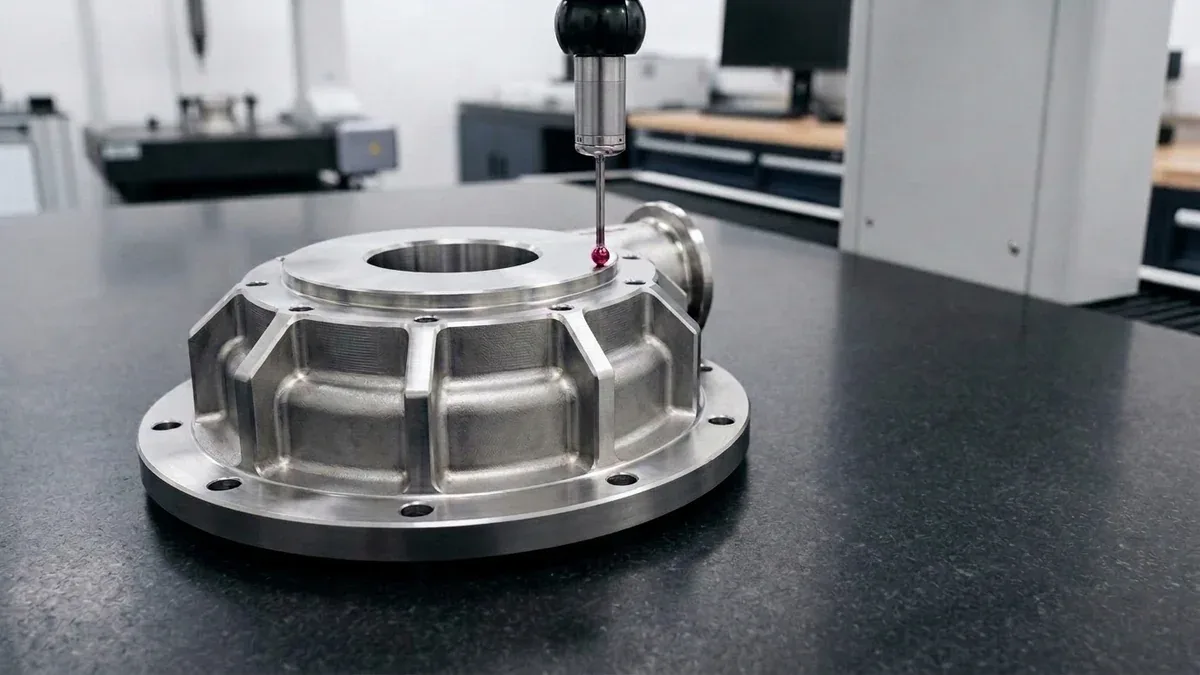
To assist mechanical designers and CAM engineers in matching part features with optimal milling kinematics, the matrix below details cutting force vectors, chip mechanisms, and achievable tolerances across industrial milling methods:
| Milling Operation | Tooling Geometry | Primary Force Vector | Optimal Material & Application | Achievable Tolerance | Surface Finish (Ra) | Key Process Rule |
|---|---|---|---|---|---|---|
| Face Milling | Indexable cutter (45° or 90° lead) + Wiper | Axial (spindle thrust) | Plates, engine blocks, structural baseplates (Al, Steel, Iron) | ±0.010 mm | 0.2 – 0.6 μm | Cutter diameter must span 1.2–1.5 × width; offset center to avoid chatter. |
| Shoulder Milling | Solid carbide 90° endmill or indexable shoulder mill | Combined radial and axial | Precision steps, bearing bores, sealing datum shoulders | ±0.010 mm | 0.4 – 0.8 μm | Ensure cutter has true 90° axial geometry to prevent wall taper between step-downs. |
| High-Feed Milling (HFM) | Large-radius curved insert (12–17° lead) | Predominantly axial | High-volume roughing of deep cavities, mold dies, titanium stock | ±0.10 – 0.20 mm | 1.6 – 3.2 μm (roughing) | Keep ap ≤ 1.2 mm; program feed per tooth fz > 1.5 mm to exploit chip thinning. |
| Trochoidal Adaptive Milling | Variable-helix micro-grain solid carbide (4–5 flutes) | Radial force with constant vector | Deep slots, thin ribs, titanium, Inconel, hardened steels | ±0.015 mm | 0.8 – 1.6 μm | Utilize full flute depth (ap = 2–3D); cap radial engagement angle at ≤ 40°. |
| 5-Axis Flank Milling (Swarf) | Tapered or cylindrical multi-flute solid carbide endmill | Peripheral radial force along line contact | Turbine blades, blisks, aerospace impellers, fluid ports | ±0.010 mm | 0.4 – 0.8 μm | Workpiece surface must be a mathematically ruled surface for full flute contact. |
| Helical Thread Milling | Single-point or multi-point profile carbide thread mill | Low radial with helical interpolation | Large threaded holes, blind holes, exotic titanium/superalloys | 6H / 6g Class | 0.6 – 1.2 μm | Execute smooth arc-in and arc-out tool entry moves to prevent thread gouging. |
5. Design for Manufacturability (DFM): Milling-Conscious Modeling Guidelines
To maximize precision and prevent excessive machining cycle times, mechanical design engineers should observe key DFM best practices tailored to milling kinematics:
- Design for Tool Access and Standard Endmill Diameters: Cavities requiring deep vertical profiling should accommodate tools with length-to-diameter ratios under 4:1. If an internal cavity is 40 mm deep, ensure corner radii are at least R5.5 mm to allow a rigid Ø 10 mm endmill to clear corners without chatter.
- Floor-to-Wall Fillet Transitions: Sharp internal floor corners require separate squaring operations with sharp tools that wear prematurely. Design floor fillets with a radius of R0.5 to R1.0 mm to match standard corner-radius bullnose endmills, which possess significantly higher fracture resistance.
- Provide Adequate Clamping Faces: Milling produces significant dynamic shear forces. Ensure components feature parallel external clamping flats or dedicated sacrificial fixturing tabs to enable rigid mechanical vise holding without workpiece distortion.
6. Technical Engineering FAQ
Climb milling initiates tooth contact at maximum chip thickness and tapers to zero, cleanly shearing metal without initial rubbing. This eliminates work-hardening, directs cutting forces downward into the machine table for rigidity, and doubles tool life compared to conventional up-milling.
High-feed milling is ideal for roughing deep pockets and cavities in mold steels and titanium. Because the small 10°–20° lead angle directs cutting forces axially straight up the spindle rather than radially across the tool shank, tool deflection is eliminated, enabling feed rates up to 5 times faster than standard endmills.
Yes. Utilizing modern high-speed CNC milling centers equipped with indexable face mills and wiper insert technology, machinists can routinely achieve surface roughness down to Ra 0.2 μm and flatness within 0.008 mm, eliminating secondary surface grinding for most hydraulic, bearing, and sealing faces.
Partner with Our Precision CNC Milling & Engineering Team
Eliminate tool deflection, residual stress distortion, and tolerance stack-up risks before production begins. Upload your 3D CAD files (STEP/IGES) and 2D GD&T drawings for a comprehensive shop-floor DFM review and custom quotation.
Upload 3D CAD for Engineering DFM & RFQ