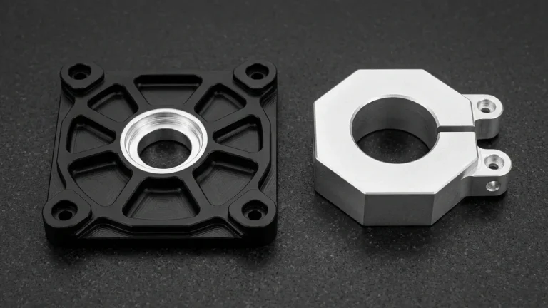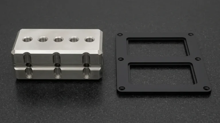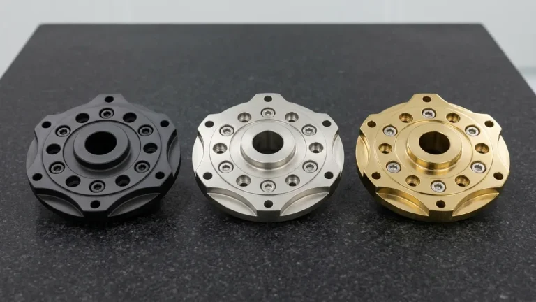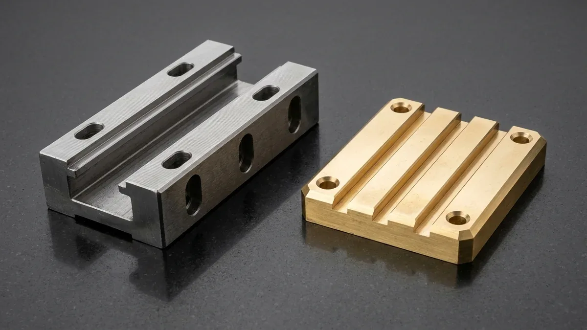
Understanding what is plain milling—also known across mechanical engineering standards as slab milling or peripheral surface milling—begins with cutter-to-workpiece kinematics. In plain milling, a cylindrical cutter rotates around a spindle axis oriented strictly parallel to the machined workpiece surface, shearing metal exclusively via helical or straight peripheral teeth.
While vertical indexable face mills handle routine plate squaring on modern machining centers, peripheral plain milling remains vital for heavy slab stock reduction, gang-milled parallel guideways, and stepped datum shoulders. On horizontal arbors (Ø40–50 mm / 1.575–1.969″) and 3-axis/4-axis CNC vertical machining centers (VMCs), peripheral cuts hold ISO 2768-mK general tolerances and ±0.010–0.020 mm (±0.0004–0.0008″) linear step precision.
At our Shenzhen CNC machining facility, our in-house engineering team evaluates every flat datum, linear guide rail, and stepped bracket to match cutter geometry with part rigidity. By balancing radial depth of cut (ae), axial engagement (ap), simply-supported arbor stiffness, and climb-shearing mechanics, we deliver chatter-free finishes averaging Ra 0.8–1.6 µm (32–63 µin).
Executive Summary & Engineering Takeaways (BLUF)
- Parallel-Axis Kinematics: Plain (slab) milling aligns the cutter axis parallel to the machined plane, engaging peripheral teeth across 20–300 mm (0.787–11.811″) widths in one pass.
- Simply-Supported Arbor Stiffness (16× Advantage): Supporting a horizontal arbor at both the BT50/ISO 50 taper and an outboard overarm bearing yields a 1 ÷ 48 deflection factor—16× stiffer than a cantilevered 1 ÷ 3 vertical end mill of equal span.
- Climb vs. Conventional Shearing: Preloaded-ballscrew CNC mills execute 90%+ of peripheral cuts via climb (down) milling, entering at hmax to seat parts downward into vises and prevent rubbing work-hardening on 304/316L stainless and Ti-6Al-4V.
- Helical Tooth Overlap: Coarse slab mills with 30°–45° helix angles maintain continuous multi-tooth engagement across 4140 and D2 steel blocks, suppressing impact chatter to hold Ra 0.8–1.6 µm (32–63 µin).
- Shop-Floor Tolerance Reality: High-speed 3-axis and 4-axis VMCs machine 80%+ of prismatic plates to ISO 2768-mK and ±0.010–0.020 mm (±0.0004–0.0008″) on critical features, handing off ±0.005 mm (±0.0002″) datums to surface grinding.
Article Engineering Navigation
- 1. What is Plain Milling? Kinematics & Arbor Architecture
- 2. Chip Thickness, MRR & Arbor Deflection Formulas
- 3. Climb (Down) vs. Conventional (Up) Milling Mechanics
- 4. Plain Milling vs. Face Milling vs. HEM End Milling
- 5. Shop-Floor 4-Step Setup & Metrology SOP
- 6. Defect Troubleshooting, DFM Rules & Grinding Handoff
- 7. When NOT to Choose Plain Milling: Trade-Offs
- 8. Technical Engineering FAQ
1. What is Plain Milling? Kinematics & Horizontal Arbor Architecture
To define what is plain milling rigorously, engineers separate peripheral cutting kinematics from axial face cutting. In plain milling, a disk or cylindrical cutter rotates around an axis parallel to the feed plane, generating a flat datum via cycloidal trochoidal arcs swept by its outer peripheral teeth.
Traditionally performed on horizontal knee-and-column or bed-type milling machines, plain milling is called slab milling when the cylindrical cutter spans a wide flat surface (50–250 mm / 1.969–9.843″). In modern CNC shops, the exact same peripheral shearing kinematics also govern side-flank milling and horizontal gang slotting.
The Horizontal Milling Arbor & Overarm Support Assembly
Unlike vertical end mills held in cantilevered collet or shrink-fit chucks, horizontal slab cutters mount centrally on a hardened, precision-ground 4140/4340 alloy steel arbor (42–48 HRC). Four coupled mechanical elements work together along the horizontal spindle axis to maintain concentricity and alignment under heavy radial loads:
- Spindle Taper & Drive Keys: A BT50, CAT50, or ISO 50 taper centers the arbor while twin drive keys transmit continuous low-RPM torsional shear torque directly into the arbor flange.
- Lapped Spacing Collars: Hardened ground collars position the cutter axially along the shaft, holding face parallelism within 0.005 mm (0.0002″) so clamping nut torque never bows the arbor.
- Keyed Cutter Bore: The slab cutter slides onto a ground journal (Ø27, Ø32, Ø40, or Ø50 mm / 1.063–1.969″) and locks via a longitudinal square keyway per DIN 138 / ANSI B94.19.
- Overarm & Outboard Support Bearing: A rigid cast-iron overarm carries a needle-roller or bronze bushing bracket supporting the outboard arbor pilot, converting a cantilever into a doubly-supported beam.
Light-Duty Straight Teeth vs. Heavy-Duty Helical Slab Cutters & Gang Setups
Light-duty plain cutters use straight peripheral teeth (helix angle β = 0°) or shallow helices (β < 20°) with fine tooth pitch for narrow keyways and light step shoulders. However, straight teeth strike the entry line simultaneously across the full cut width, causing periodic impact spikes and chatter.
Heavy-duty slab mills solve this by combining coarse tooth pitch with steep 30°–45° helix angles (and up to 60° on indexable porcupine cutters). As the cutter rotates, the helical edge engages progressively across the workpiece width like a cylindrical shear, keeping multiple flutes in cut simultaneously.
In batch production, machinists mount multiple cylindrical plain cutters and side-and-face cutters on one arbor for gang milling, machining stepped guide rails and central channels in one pass. Pairing interlocking left-hand and right-hand helical cutters cancels axial spindle thrust and prevents junction ridges.
2. Peripheral Chip Mechanics, MRR & Horizontal Arbor Deflection Formulas
Engineering a chatter-free plain milling operation requires calculating four coupled physical quantities: maximum uncut chip thickness (hex), cycloidal feed-mark cusp height (Rth), volumetric material removal rate (Q), and horizontal arbor bending deflection (δarbor). Our CAM engineers verify these relationships before releasing heavy surfacing or gang-slotting programs.
1. Radial Engagement Angle, Uncut Chip Thickness, Cusp Height & MRR
As a cylindrical peripheral cutter of diameter D (mm / in) engages a radial depth of cut ae (mm / in), the swept engagement angle φs, maximum uncut chip thickness hex, and theoretical cycloidal cusp height Rth follow classical circular-arc peripheral milling kinematics:
hmax (hex) = fz × sin(φs) = 2 × fz × √((ae ÷ D) × (1 − (ae ÷ D))) | hm ≈ fz × √(ae ÷ D)
RCTF = fz ÷ hex = 1 ÷ (2 × √((ae ÷ D) × (1 − (ae ÷ D))))
Rth ≈ (fz2 ÷ (4 × D)) × 1,000 [µm] (or fn2 ÷ (4 × D) under once-per-rev TIR)
Q = (ap × ae × vf) ÷ 1,000 [cm³⁄min] where vf = n × z × fz [mm⁄min]
Here, fz is feed per tooth (mm/tooth), ap is axial cut width (mm / in), z is tooth count, and n is spindle speed (RPM). When radial engagement is shallow (ae ÷ D < 0.25), hex and mean chip thickness hm drop sharply, requiring radial chip-thinning factor (RCTF) feed compensation to prevent rubbing.
2. Simply-Supported Horizontal Arbor Deflection vs. Cantilevered End Mill
A vertical end mill overhanging by stickout L acts as a cantilevered beam (factor 1 ÷ 3), whereas a horizontal arbor supported at both the spindle taper and outboard overarm bearing acts as a simply-supported beam (factor 1 ÷ 48 at mid-span):
δcantilever = (Fr × Lstickout3) ÷ (3 × E × I) = 16 × δarbor (for identical L and d)
Where Fr is radial cutting force (N / lbf), Larbor is bearing span (mm / in), E is steel Young’s modulus (210,000 MPa / 30.46 Mpsi), and darbor is arbor diameter. Because I scales with darbor4, stepping up from a Ø32 mm to a Ø50 mm arbor increases bending stiffness by 5.96×.
3. Worked Shop-Floor Calculation (4140 Alloy Steel Guide Block)
Consider slab milling a 120 mm (4.724″) wide pre-hardened 4140 steel linear guide block (28–32 HRC) using a Ø100 mm (3.937″) helical slab mill (z = 8 teeth, β = 35°) at mid-span on a darbor = 40 mm (1.575″) arbor with span Larbor = 260 mm (10.236″):
- Chip Load, Cusp Height & MRR: With ae = 4.0 mm (0.157″), ap = 120 mm (4.724″), n = 350 RPM (vc = 110 m/min / 361 SFM), and fz = 0.18 mm/tooth (0.0071 in/tooth), engagement angle φs = arccos(0.92) = 23.07°, hex = 2 × 0.18 × √(0.04 × 0.96) = 0.0705 mm (0.0028″), mean chip hm ≈ 0.18 × √0.04 = 0.036 mm (0.0014″), RCTF = 2.55×, ideal tooth cusp Rth ≈ (0.182 ÷ (4 × 100)) × 1,000 = 0.081 µm (3.2 µin), table feed vf = 504 mm/min (19.84 in/min), and Q = 241.9 cm³/min (14.76 in³/min).
- Arbor Deflection: With I = 125,664 mm4 (0.3019 in4) and radial force Fr = 4,200 N (944 lbf), roughing deflection δarbor = (4,200 × 2603) ÷ (48 × 210,000 × 125,664) = 0.0583 mm (0.0023″), dropping below 0.006 mm (0.00024″) during a 0.4 mm (0.016″) finishing pass.
3. Climb (Down) Milling vs. Conventional (Up) Milling in Peripheral Cutting
Because peripheral teeth sweep an eccentric trochoidal arc through the metal stock, table feed direction relative to cutter rotation directly governs chip formation, shear-zone heat evacuation, and workholding fixture stability. Selecting the wrong milling direction on work-hardening alloys can chip or glaze carbide edges rapidly.
Why Climb (Down) Milling Dominates Modern CNC Peripheral Machining
In climb milling (down milling), the cutter periphery moves in the same direction as the table feed, biting in at maximum chip thickness (hmax) and exiting at zero thickness (h = 0) along the finished floor. In our CNC milling services shop, climb milling is standard for three reasons:
- Work-Hardening Prevention: Immediate shear engagement at hmax > 0.05 mm (0.002″) eliminates entry rubbing and strain-hardening on austenitic 304/316L stainless steel and Ti-6Al-4V Grade 5 titanium.
- Downward Clamping Vector: Vertical cutting forces press the workpiece firmly into the precision machine vise or fixture bed, suppressing thin-plate flutter.
- Rearward Chip Evacuation: Over 80% of shear heat exits behind the cutter inside the thick initial chip, preventing chip recutting and extending tool life by 35%–60%.
When Conventional (Up) Milling Remains Mandatory
In conventional milling (up milling), the workpiece feeds directly against cutter rotation so uncut chip thickness grows gradually from zero (h = 0) at entry to hmax at exit. Despite initial entry rubbing and upward lifting forces, conventional milling remains mandatory in two specific shop-floor cases:
- Abrasive Cast & Hot-Rolled Scale: On hot-rolled Q235B/A36 steel mill scale or sand-cast A356 aluminum and ductile iron skins, entering from underneath the hard oxide layer pries the crust upward without chipping carbide edges.
- Manual Leadscrew Backlash: On older horizontal mills without preloaded ballscrews, opposing tangential forces keep the leadscrew nut seated against the driving thread flank.
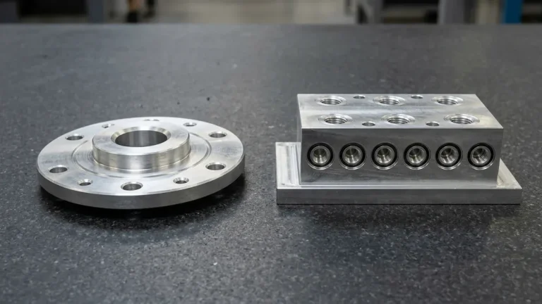
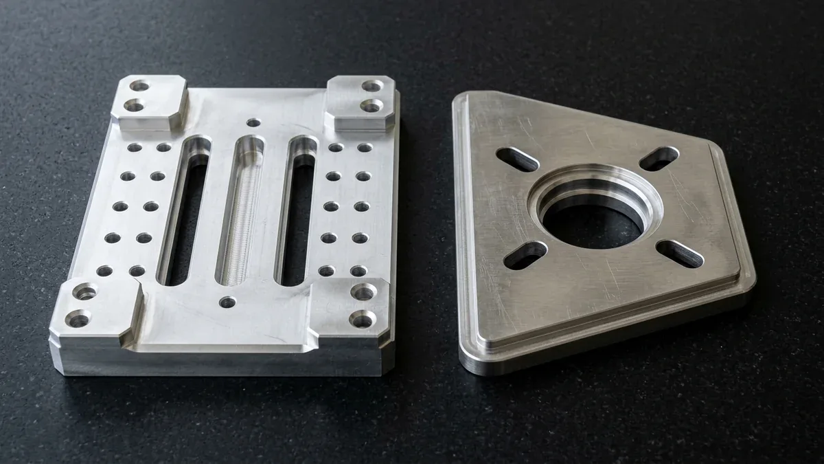
Below, two peripheral climb-milled plates rest flat on our black granite surface plate. The left 6061-T6 aluminum fixture baseplate features four raised corner pads, three longitudinal milled slots, and a dowel grid, while the right 304 stainless steel tapered gusset adapter plate shows a stepped pilot bore, four obround slots, and a peripheral rabbet shoulder (±0.015 mm / ±0.0006″).
4. Plain Milling vs. Face Milling vs. High-Efficiency Peripheral End Milling
In our in-house CNC machining cells, high-speed 3-axis and 4-axis vertical machining centers (Brother, Fanuc Robodrill, Haas, and Mazak VMCs with Kurt precision vises or contoured aluminum soft jaws) handle 75%–85%+ of prismatic brackets, plates, and manifolds. Simultaneous 5-axis CNC is reserved strictly for impellers, blisks, and compound-angle aerospace contours.
When engineering flat structural datums, parallel guideway slots, or stepped mounting shoulders, our process engineers select among four production milling methods across our in-house CNC equipment fleet: Horizontal Plain/Gang Milling, 45° Indexable Face Milling, 90° Square-Shoulder Milling, and Solid-Carbide High-Efficiency Peripheral End Milling (HEM).
| Parameter | Horizontal Plain (Slab / Gang) | 45° Indexable Face Milling | 90° Square-Shoulder Milling | Solid-Carbide Peripheral HEM | Recommended Application / When to Choose |
|---|---|---|---|---|---|
| Spindle Axis Orientation | Parallel (0°) to machined plane | Perpendicular (90°) to plane | Perpendicular to floor; parallel to wall | Perpendicular to floor; peripheral flank cut | Plain/Gang for multi-slot profiles; Face Mill for open top datums |
| Active Cutting Edges | Cylindrical helical periphery (β = 30°–45°) | 45° lead inserts + bottom wiper flats | 90° peripheral + bottom corner edges | Full flute depth (ap = 2×D), low ae (10% D) | 45° Face Mill for low vibration on 3-axis VMCs |
| Rigidity & Deflection Mode | Simply-supported arbor (1 ÷ 48 factor) | Direct short stub arbor; highest axial stiffness | Radial load pushes tool from 90° wall | Cantilevered shank (1 ÷ 3); low radial force | Outboard arbor for wide gang cuts > 100 mm (3.937″) |
| Flatness Zone per 100 mm (ISO 1101) | 0.015–0.030 mm (0.0006–0.0012″) | 0.008–0.015 mm (0.0003–0.0006″) | 0.012–0.020 mm (0.0005–0.0008″) | 0.010–0.020 mm (0.0004–0.0008″) | Face Milling + Wiper or Grinding for tight sealing faces |
| Surface Finish & Lay | Ra 0.8–3.2 µm (32–125 µin); transverse waves | Ra 0.4–1.6 µm (16–63 µin); cross-hatch arcs | Ra 0.8–1.6 µm (32–63 µin); circular sweep | Ra 0.4–1.2 µm (16–47 µin); fine flank lay | Peripheral flank pass for smooth vertical shoulders |
| Relative Cost Index | 1.3× setup; 0.7× cycle in gang production | 1.0× baseline on 3-axis CNC VMC | 1.1× (multiple stepovers on wide stock) | 0.9× on deep pockets & contoured profiles | Gang Plain Milling for ≥ 50-pc rail lots; VMC for 1–50 pcs |
5. Shop-Floor SOP: 4-Step Setup & Metrology Protocol for Peripheral Milling
Whether running horizontal arbor gang cutters on alloy steel guide blocks or executing peripheral flank finishing in our precision CNC machining department, cutter setup runout directly governs cyclical surface waviness and dimensional accuracy. Our shop-floor machinists enforce a strict four-step Standard Operating Procedure (SOP):
- Verify Arbor & Toolholder Radial Runout (TIR ≤ 0.008 mm / 0.0003″): Clean the spindle taper, arbor journal, and ground spacing collars ultrasonically. Check radial TIR with a lever dial test indicator before and after torquing the arbor nut so collar non-parallelism (≤ 0.005 mm / 0.0002″) never bows the shaft.
- Maximize Workholding Span (≥ 70%) & Minimize Outboard Bearing Distance: Seat blocks flat on precision parallels inside a Kurt vise or custom soft jaws spanning at least 70% of part length, and slide the overarm outboard bearing bracket within 15–25 mm (0.59–0.98″) of the cutter hub.
- Program Helical Tooth Overlap & Chip-Thinning Compensation: Maintain helical overlap ratio Ro = (ap × tan(β)) ÷ (π × D ÷ z) ≥ 1.25 for continuous tooth engagement, and apply radial chip-thinning feed multipliers whenever ae ≤ 0.10 × D to keep hex ≥ 0.04 mm (0.0016″).
- Execute Profilometry & CMM Datum Verification: After thermal stabilization at 20 °C ± 1 °C (68 °F ± 1.8 °F), measure transverse roughness via a diamond-stylus profilometer (Mitutoyo SJ-210 / SJ-410 per ISO 4287 / ASME B46.1) and verify datum flatness and bore squareness on our Zeiss Contura bridge CMM.
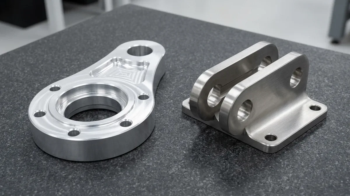
Peripheral milling is equally vital when contouring linkage flanks, pocketing webs, and gang-slotting clevis yokes for robotics and automation assemblies. Below, a 7075-T6 aluminum twin-bore bearing carrier link plate with a pocketed web rests flat on our granite plate beside a 304 stainless steel twin-ear clevis fork yoke featuring a deep peripheral-milled slot and coaxial reamed pin bores.
6. Defect Troubleshooting, DFM Rules & Post-Milling Grinding Transitions
Even on rigid CNC machines, peripheral plain and side milling can exhibit dimensional or surface defects if radial forces, axial thrust, or residual plate stresses are mismanaged. The matrix below pairs each shop-floor anomaly with its quantitative threshold and DFM prevention rule.
| Observed Defect | Mechanical Root Cause | Quantitative Threshold | Corrective Shop Action | Recommended Application / DFM Prevention Rule |
|---|---|---|---|---|
| Mid-Width Convex Crown (“Arbor Belly”) | Radial force Fr bends horizontal arbor away at mid-span | Crown > 0.025 mm (0.0010″) when Larbor ÷ darbor > 7:1 | Upgrade from Ø32 to Ø50 mm arbor; add 0.25 mm (0.010″) spring pass | Switch wide flat plates (> 100 mm / 3.937″) to VMC wiper face milling or surface grinding |
| Periodic Chatter Scallops | Low-helix teeth (< 20°) excite arbor or thin-wall resonance | Waviness Wt > 6.3 µm (250 µin); overlap ratio Ro < 1.0 | Use 30°–45° helical cutter or variable-pitch carbide end mill | Design walls ≥ 1.5 mm (0.059″) in aluminum and ≥ 2.0 mm (0.079″) in stainless steel |
| Work-Hardened Glaze & Notch Wear | Conventional milling or hex < 0.02 mm (0.0008″) causes rubbing | Surface hardness spike +80 to +120 HV on 304/316L and Ti-6Al-4V | Enforce climb milling; apply radial chip-thinning to keep hex ≥ 0.05 mm | Specify 303 stainless for non-welded blocks when corrosion specs permit |
| Axial Thrust Step Drift | Single-hand high helix creates axial load Fa = Ft × tan(β) | Shoulder drift > ±0.030 mm (±0.0012″) under heavy cuts | Mount opposing left/right herringbone cutters to cancel axial thrust | Use interlocking staggered-tooth cutters for deep precision clevis slots |
| Unclamped Plate Bow / Warpage | Asymmetric single-side stock removal releases rolling stress | Bow > 0.08 mm per 200 mm (0.0031″ per 7.87″) after vise release | Rough-mill top and bottom faces symmetrically (Flip-A / Flip-B) | Specify pre-stretched 6061-T651 or 7075-T651 plate stock for flat plates |
Handoff to Precision Surface Grinding & Ex-Factory Lead Times
When drawings call for ±0.005 mm (±0.0002″) linear thickness tolerances or 0.005 mm (0.0002″) datum flatness and parallelism on hardened tool steel (D2 / SKD11 at 58–62 HRC, H13 at 48–52 HRC) or 4140 guideways at Ra 0.1–0.4 µm (4–16 µin), we rough-mill leaving a 0.15–0.25 mm (0.006–0.010″) allowance, heat-treat, and finish in our precision surface grinding cell.
Our Ex-Factory Production & Inspection Turnaround (separated from 3–5 business days DHL/FedEx/UPS air transit) is 4–8 business days for bare CNC prototypes, 7–12 business days with surface finishing (MIL-A-8625 Type II/III anodizing, ASTM A967 passivation, or grinding), and 7–30 business days for low-to-mid volume production.
7. When NOT to Choose Plain Milling: Process Limitations & Trade-Offs
Despite its high volumetric efficiency on long horizontal steel slabs and gang-milled guideway slots, traditional horizontal arbor plain milling introduces geometric access constraints and mid-span deflection trade-offs. Process engineers and hardware buyers should avoid plain slab milling and specify an alternative process in four specific scenarios:
- 1. Wide Flat Plates Requiring ≤ 0.010 mm (0.0004″) Datum Flatness: Mid-span arbor deflection leaves a slight convex crown on wide slabs; choose 45° indexable wiper face milling on a 3-axis VMC or precision surface grinding.
- 2. Blind Internal Pockets & Tight Vertical Corner Radii: Large Ø63–160 mm (2.48–6.30″) arbor cutters cannot plunge into closed cavities or clear small vertical corners; choose 3-axis/4-axis VMC solid-carbide end milling.
- 3. Thin-Walled Sheet Metal Brackets (t = 0.5–3.0 mm / 0.020–0.118″): Peripheral milling forces cause severe sheet springback and vibration; use fiber laser cutting and CNC press-brake bending (verified via checking fixtures, 90° knife-edge squares, and pin gauges).
- 4. Narrow Through-Slots (≤ 1.5 mm / 0.059″) or Sharp R = 0 Corners: Slitting saws drift on deep sub-millimeter flexures; specify Wire EDM for through-slots or Sinker EDM for blind sharp corners.
🔗 Related CNC Milling Engineering Guides
8. Technical Engineering FAQ
In plain milling, the cutter axis rotates strictly parallel to the workpiece surface and removes metal exclusively with peripheral helical teeth. Conversely, face milling orients the spindle perpendicular to the workpiece, cutting primarily with peripheral lead edges and flat bottom wiper inserts.
Climb milling engages each tooth at maximum chip thickness and exits at zero, directing vertical cutting forces downward into the vise bed while preventing rubbing work-hardening on 304 stainless steel. Conventional milling is reserved strictly for breaking through abrasive sand-cast or hot-rolled oxide skins.
Machinists minimize arbor deflection by selecting the largest standard arbor diameter (40–50 mm / 1.575–1.969 in) and clamping the overarm outboard support bearing within 20 mm (0.787 in) of the cutter hub. Using 30°–45° helical slab mills also distributes radial cutting loads smoothly.
Standard CNC peripheral and slab milling holds general linear tolerances to ISO 2768-mK, critical step dimensions to ±0.010–0.020 mm (±0.0004–0.0008 in), and datum flatness within 0.015–0.025 mm (0.0006–0.0010 in) at Ra 0.8–1.6 µm (32–63 µin). Tighter ±0.005 mm (±0.0002 in) features transition to surface grinding.
Ready to Optimize Your Custom Parts for Precision Manufacturing?
Upload your 3D STEP/IGES files and 2D GD&T drawings for a comprehensive DFM review covering datum flatness, peripheral vs. face milling selection, and post-milling surface grinding tolerances. Our in-house CNC engineering team in Shenzhen will evaluate your part geometry and provide a detailed manufacturing quotation.
Request a Technical DFM & Custom Quote →