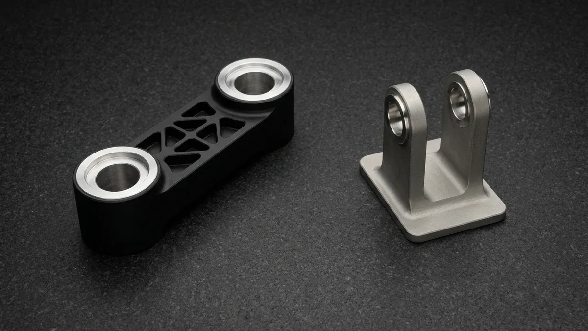
Building a custom machined exoskeleton robot demands structural components that balance high specific stiffness against strict distal-limb mass limits. Wearable gait-rehabilitation suits and industrial lumbar-support frames subject hip, knee, and ankle joints to repetitive multi-axis bending moments exceeding 120 N·m (88.5 lb·ft) across millions of gait cycles.
Through Computer Numerical Control (CNC) milling, Swiss-type turning, and Electrical Discharge Machining (EDM), our in-house CNC machining facility holds ±0.010 mm (±0.0004 in.) bearing-bore tolerances. This engineering guide details alloy selection, rotational-inertia math, 4-bar knee backlash control, and Design for Manufacturability (DFM) rules for wearable robotics.
Executive Summary & Engineering Takeaways (BLUF)
- Alloy Allocation by Load Zone: Specify pre-stretched 7075-T651 aluminum (503 MPa / 73.0 ksi yield) for iso-grid femoral and tibial struts, Ti-6Al-4V Grade 5 (880 MPa / 127.6 ksi yield) for polycentric knee clevis yokes, 17-4PH H900 stainless steel (1,170 MPa / 170.0 ksi yield) for joint torque flexures, and PEEK for dielectric sensor spacers.
- Kinematic Tolerance & Backlash Architecture: Hold ISO 286 H6/H7 (+0.019 / -0.000 mm on Ø68 mm harmonic cross-roller seats) with coaxiality ≤ 0.010 mm (0.0004 in.) Total Indicator Reading (TIR) via precision CNC milling, while assigning default tolerances per ISO 2768-mK (±0.10 mm to ±0.20 mm) to non-mating webs.
- Skin-Safe Tribology & Wear Protection: Apply 50 µm (0.0020 in.) Type III hardcoat anodizing (micro-hardness 450–550 HV0.05) with silicone plug masking on aluminum bores, paired with PVD DLC (Diamond-Like Carbon, 2–4 µm, μ < 0.10) or ASTM A967 citric passivation on titanium and stainless steel pins.
- Ex-Factory Turnaround & Verification: Bare-machined exoskeleton prototypes ship in 4 ~ 8 Business Days, while multi-axis assemblies requiring Type III hardcoat anodizing, PVD DLC coating, and full Coordinate Measuring Machine (CMM) verification ship in 7 ~ 12 Business Days (Ex-Factory Production & Inspection Turnaround, excluding 3 ~ 5 Days air transit).
Article Engineering Navigation
- 1. Biomechanical Kinematics & Distal Inertia Limits in a Machined Exoskeleton Robot
- 2. Material Selection Matrix: 7075-T651 Aluminum vs Ti-6Al-4V vs 17-4PH vs PEEK
- 3. Quantitative Derivation: Distal Limb Inertia & 4-Bar Knee Linkage Backlash
- 4. Multi-Axis CNC Machining Workflows, Feeds & Speeds for Wearable Joints
- 5. Surface Finishing, Tribology & Skin-Safe Wear Protection
- 6. Metrology Verification, CMM Probing & Shop-Floor Troubleshooting
- 7. Technical Engineering FAQ
1. Biomechanical Kinematics & Distal Inertia Limits in a Machined Exoskeleton Robot
A machined exoskeleton robot is a wearable electromechanical orthosis whose load-bearing linkages, actuator housings, and polycentric joints are subtractively milled and turned from wrought metal billets to parallel human limb kinematics. However, asymmetric joint eccentricities above 0.025 mm (0.0010 in.) generate parasitic shear forces against biological knee and hip cartilage.
Unlike stationary industrial manipulators in custom robotics and automation manufacturing or our general robotics prototyping and precision manufacturing guide, wearable exoskeletons mount their power supply on the human torso. Every gram added at the ankle multiplies hip swing rotational inertia quadratically with limb radius, accelerating operator metabolic exhaustion.
Why Do Wearable Exoskeletons Require Billet CNC Machining Instead of Metal 3D Printing?
Wrought billet precision CNC machining outperforms Direct Metal Laser Sintering (DMLS) for primary exoskeleton linkages because cold-rolled 7075-T651 and Ti-6Al-4V plates possess homogeneous grain structures free from subsurface lack-of-fusion pores. Under fully reversed gait bending loads exceeding 5 × 10⁶ cycles, unhipped additive metal parts suffer up to 40% lower high-cycle fatigue endurance.
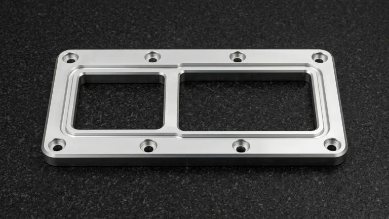
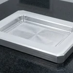
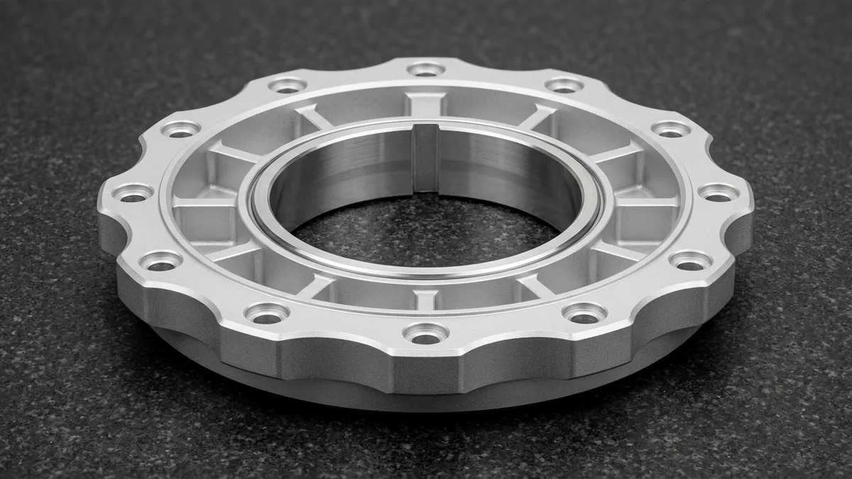
At the hip and knee actuation nodes, compact strain-wave harmonic reducers and frameless brushless rotors must seat inside ultra-thin stator rings without radial eccentricity. As shown in the clear-anodized 7075-T651 hip harmonic actuator stator mount on the black granite plate below, scalloped outer flanges shed peripheral mass while preserving an H6 cross-roller bearing raceway.
2. Material Selection Matrix: 7075-T651 Aluminum vs Ti-6Al-4V vs 17-4PH vs PEEK
Selecting structural alloys for a machined exoskeleton robot requires evaluating lightweight metal specific strength and stiffness (σ_y / ρ and E / ρ) alongside notched fatigue endurance across each anatomical load zone. Specifying a single alloy across the entire wearable frame either inflates distal swing weight or causes premature fretting failure at high-stress clevis pins.
For long femoral and tibial struts, pre-stretched 7075-T651 aluminum delivers 503 MPa (73.0 ksi) yield strength—nearly double 6061-T651—allowing 1.5 mm (0.059 in.) iso-grid webs. For alloy trade-offs see our 6061 vs 7075 aluminum selection guide, and for asymmetric billet stress relief consult our guide to preventing residual-stress deformation in CNC milling aluminum.
Conversely, engineers should not specify 7075-T651 for unbushed double-shear pivot pins or thin-section pelvic yokes subject to multi-axial shock, because aluminum suffers rapid galling and lacks a true fatigue endurance limit. In those compact high-stress joints, Grade 5 Ti-6Al-4V or H900 precipitation-hardened 17-4PH stainless steel prevents catastrophic brittle fracture.
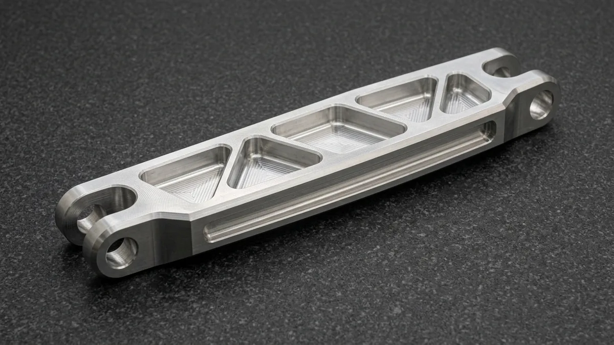
Similarly, avoid Titanium Grade 5 for long stiffness-governed thigh beams where aluminum’s lower density achieves higher bending rigidity per gram at one-fourth the machining cost. The as-machined 7075-T651 femoral strut on the granite surface plate below illustrates how triangular iso-grid pocketing and recessed cable channels maximize bending stiffness before comparing materials in Table 1.
| Material Grade | Density (g/cm³ / lb/in³) | Yield Strength (MPa / ksi) | Elastic Modulus (GPa / Mpsi) | Specific Strength (kN·m/kg) | Relative CNC Cost | Recommended Application / When to Choose (and Avoid) |
|---|---|---|---|---|---|---|
| Aluminum 7075-T651 | 2.81 g/cm³ (0.101 lb/in³) | 503 MPa (73.0 ksi) | 71.7 GPa (10.4 Mpsi) | 179.0 kN·m/kg | 1.3× | Choose for iso-grid femoral/tibial struts and harmonic actuator housings; avoid for unanodized sliding contact or welded subframes. |
| Aluminum 6061-T651 | 2.70 g/cm³ (0.098 lb/in³) | 276 MPa (40.0 ksi) | 68.9 GPa (10.0 Mpsi) | 102.2 kN·m/kg | 1.0× (Baseline) | Choose for early proof-of-concept frames, battery enclosures, and low-load sensor brackets; avoid for thin-wall high-torque hip links. |
| Titanium Ti-6Al-4V (Gr 5) | 4.43 g/cm³ (0.160 lb/in³) | 880 MPa (127.6 ksi) | 113.8 GPa (16.5 Mpsi) | 198.6 kN·m/kg | 3.8× – 4.5× | Choose for polycentric knee clevis yokes, pelvic load rings, and sweat-exposed skin-contact joints; avoid for long stiffness-driven beams. |
| Stainless 17-4PH (H900) | 7.80 g/cm³ (0.282 lb/in³) | 1,170 MPa (170.0 ksi) | 197.0 GPa (28.6 Mpsi) | 150.0 kN·m/kg | 2.2× – 2.8× | Choose for multi-axis joint torque-sensor flexures, splined output shafts, and ground clevis pins; avoid for large distal limb frames due to mass. |
| PEEK (Unfilled / CF30) | 1.31–1.40 g/cm³ (0.047–0.051 lb/in³) | 100–230 MPa (14.5–33.4 ksi) | 3.6–22.0 GPa (0.52–3.19 Mpsi) | 76.3–164.3 kN·m/kg | 2.5× – 3.2× | Choose for dielectric EMG sensor mounts, low-friction thrust washers, and ISO 10993 skin-contact cuff sliders; avoid for primary bearing press-fits. |
3. Quantitative Derivation: Distal Limb Inertia & 4-Bar Knee Linkage Backlash
Quantifying distal rotational inertia and polycentric linkage clearance prior to CAM programming prevents actuator saturation and trajectory lag in a machined exoskeleton robot. Because human gait swing phases require rapid angular accelerations up to 25 rad/s², unoptimized distal mass and loose pin tolerances degrade closed-loop impedance control.
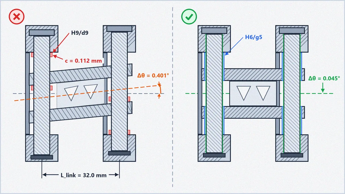
By the parallel-axis theorem (I_hip = I_cm + m · d²), relocating 150 g (0.33 lb) from a distal ankle bracket (d = 0.78 m) to the hip (d = 0.12 m) reduces swing inertia by 97.6%. Simultaneously, polycentric 4-bar knee linkages—illustrated in the CAD schematic below—accumulate pin-to-bore clearances across four pivots into free angular backlash.
📐 Engineering Formula & Shop-Floor Quantitative Derivation: Exoskeleton Swing Inertia & 4-Bar Knee Backlash
(1) Parallel-Axis Hip Rotational Inertia: I_hip = (1/12) · m · L² + m · d² | τ_swing = I_hip · α
(2) Polycentric 4-Bar Link Angular Backlash: Δθ_backlash ≈ (c_1 + c_2) / L_link | Δx_ankle = R_tibial · Δθ_backlash
- m & L: Tibial strut mass (kg) and span length L = 0.36 m (14.17 in.); center-of-mass distance from hip axis d = 0.65 m (25.59 in.); peak swing angular acceleration α = 25 rad/s².
- c_1, c_2 & L_link: Diametral pin-to-bore clearances (mm) at opposing Ø8.000 mm (0.3150 in.) pivots on an anterior-posterior knee link of length L_link = 32.0 mm (1.260 in.); distal ankle radius R_tibial = 400 mm (15.75 in.).
Worked Shop-Floor Example:
• Part A — Iso-Grid Strut Pocketing Inertia Reduction: A solid 7075-T651 tibial bar (m_solid = 0.620 kg / 1.367 lb) yields I_hip,solid = (1/12)(0.620)(0.36)² + (0.620)(0.65)² = 0.006696 + 0.261950 = 0.268646 kg·m², demanding τ_solid = 0.268646 × 25 = 6.716 N·m (4.953 lb·ft). After 3-axis CNC iso-grid pocketing (58% mass removal to m_iso = 0.260 kg / 0.573 lb), I_hip,iso = 0.002808 + 0.109850 = 0.112658 kg·m² and τ_iso = 2.816 N·m (2.077 lb·ft)—cutting parasitic hip swing torque by 3.900 N·m (58.1%).
• Part B — 4-Bar Knee Pin Fit Backlash Control: With standard drilled H9/d9 fits (max clearance c = 0.112 mm / 0.0044 in. per joint), angular backlash reaches Δθ = (2 × 0.112) / 32.0 = 0.00700 rad (0.401°), causing Δx_ankle = 400 × 0.00700 = 2.80 mm (0.110 in.) of distal cuff slap. Upgrading to CNC line-bored and reamed H6/g5 fits (mean clearance c = 0.0125 mm / 0.0005 in. per joint) restricts play to Δθ = (2 × 0.0125) / 32.0 = 0.000781 rad (0.045°) and Δx_ankle = 0.31 mm (0.012 in.)—an 88.9% reduction in kinematic joint backlash.
To eliminate even that residual 0.045° sliding clearance in high-torque rehabilitation knees, engineers press-fit needle roller bearings or bronze bushings into H7 housing bores. For detailed radial interference equations and thermal assembly allowances, refer to our ISO 286 press-fit tolerance and interference mechanics guide.
4. Multi-Axis CNC Machining Workflows, Feeds & Speeds for Wearable Joints
Manufacturing a machined exoskeleton robot cost-effectively requires matching each component’s geometric complexity to the right machine kinematics across 3-axis, 4-axis, and simultaneous 5-axis CNC centers. Over-specifying simultaneous 5-axis milling for planar femoral struts or flat sensor plates inflates hourly machine rates by 2× to 4× without improving dimensional accuracy.
In our in-house CNC machining facility, over 75% of exoskeleton components—including iso-grid limb struts, encoder brackets, and battery frames—are milled on high-speed 3-axis and 4-axis Brother and Fanuc vertical machining centers. We reserve simultaneous 5-axis CNC machining for compound-angle pelvic yokes and anatomical knee clevises, while turning shouldered pivot pins on Star Swiss-type CNC turning centers.
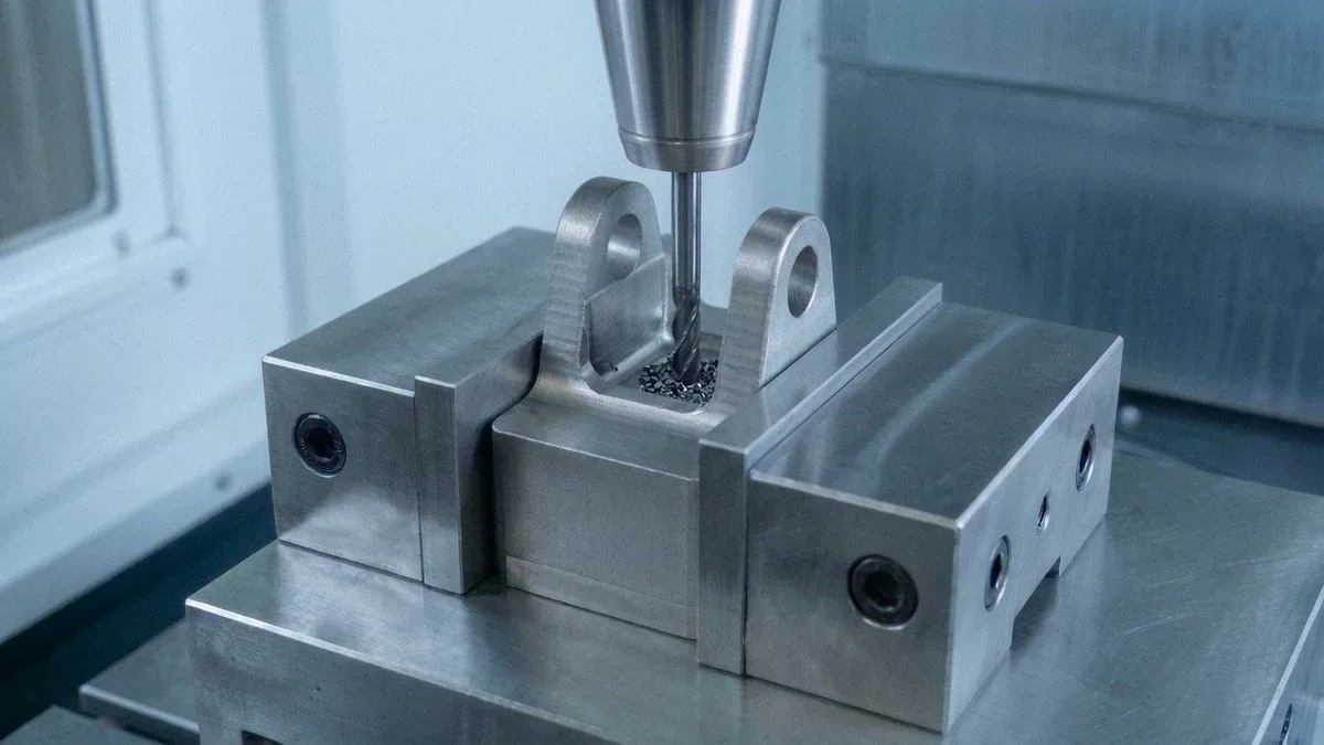
When pocketing 1.5 mm (0.059 in.) exoskeleton webs, specify internal corner radii R ≥ 1/3 of pocket depth to prevent tool chatter; see our guide on sharp internal corners and L³/D⁴ end-mill deflection and our thin-walled CNC machining fixturing guide. The setup below shows a Ti-6Al-4V polycentric knee clevis clamped in an enclosed-screw precision machine vise.
Step-by-Step Shop-Floor Machining Sequence for Distortion-Free Exoskeleton Links
Because pocketed 7075-T651 femoral links and CNC machined Ti-6Al-4V titanium joint yokes lose over 70% of their initial billet volume, single-pass hogging releases residual rolling stresses that bow thin webs beyond ±0.15 mm (±0.006 in.). Our machinists execute a four-stage stress-balanced machining protocol to lock in ±0.010 mm (±0.0004 in.) bearing-to-bearing center distances:
- Rough Symmetrically with Trochoidal Toolpaths: Alternating between Op-10 and Op-20 billet faces, remove 85% of pocket stock using dynamic trochoidal milling (a_e = 8%–10% D), leaving a uniform 0.50 mm (0.020 in.) semi-finishing allowance across all iso-grid ribs and bearing bosses.
- Stabilize and Unclamp for Elastic Stress Relaxation: Release vise clamping pressure and allow roughed 7075-T651 or Ti-6Al-4V blanks to equilibrate for 4 to 12 hours (restricting any 7075-T651 thermal stabilization soak strictly to ≤ 100–110 °C / 212–230 °F to avoid over-aging the T6 temper) so neutral-axis bow manifests prior to finishing.
- Re-Indicate Datums in Conformal Soft Jaws: Machine contoured aluminum soft jaws or vacuum-chuck nests matching the semi-finished profile, clamping at controlled torque (15–20 N·m) with zero radial jaw lift to re-cut primary datum planes flat within 0.005 mm (0.0002 in.).
- Bore and Ream Coaxial Joint Seats in One Setup: Finish-interpolate and fine-bore opposing H6/H7 harmonic reducer seats and clevis pin holes in a single indexed 3+2 or simultaneous 5-axis setup, maintaining 0.010 mm (0.0004 in.) TIR coaxiality and Ra 0.4–0.8 µm (16–32 µin.) bearing wall finish.
| Exoskeleton Material | Cutting Tool & Coating | Cutting Speed V_c (m/min / SFM) | Feed per Tooth f_z (mm / in.) | Radial Stepover a_e (% Tool Ø) | Coolant & Chip Control | Recommended Application / When to Choose |
|---|---|---|---|---|---|---|
| 7075-T651 Aluminum | 3-flute 45° helix carbide, ZrN or uncoated polished flutes | 280–450 m/min (920–1,475 SFM) | 0.06–0.14 mm (0.0024–0.0055 in.) | 8%–15% D (rough); 2%–5% D (finish) | 8% Brix flood emulsion or air-blast MQL for chip evacuation | Choose for high-speed 3-axis/4-axis pocketing of femoral struts and harmonic drive housings. |
| Ti-6Al-4V (Grade 5) | 5-flute variable-helix carbide, AlTiN / TiAlSiN nano-coating | 45–65 m/min (150–215 SFM) | 0.03–0.06 mm (0.0012–0.0024 in.) | 6%–10% D (strictly climb milling) | 70 bar (1,000 psi) through-spindle coolant (TSC) to stop work hardening | Choose for 5-axis polycentric knee clevis yokes, pelvic hip brackets, and high-fatigue load pins. |
| 17-4PH Stainless (H900) | 4-flute differential-pitch carbide, AlTiN PVD coating | 70–110 m/min (230–360 SFM) | 0.04–0.08 mm (0.0016–0.0031 in.) | 8%–12% D | High-pressure synthetic flood coolant; zero corner dwelling | Choose for multi-axis strain-gauge torque-sensor flexures, splined shafts, and ground bushings. |
| Medical / Virgin PEEK | 2-flute high-rake polished carbide or PCD diamond cutter | 150–250 m/min (490–820 SFM) | 0.05–0.10 mm (0.0020–0.0039 in.) | 15%–30% D | Compressed cold air blast or pure deionized water mist (oil-free) | Choose for dielectric sensor isolators, low-friction thrust washers, and skin-contact cuff slides. |
5. Surface Finishing, Tribology & Skin-Safe Wear Protection
Surface finishing for a machined exoskeleton robot serves three concurrent engineering functions: preventing aluminum-to-titanium adhesive galling, shielding structural frames from human sweat corrosion, and maintaining exact bearing-bore interference fits. Neglecting oxide film buildup during MIL-A-8625 Type III hardcoat anodizing shrinks H7 bearing seats by 0.050 mm (0.0020 in.) on diameter.
Because Type III hardcoat anodizing grows 50% inward and 50% outward, a 50 µm (0.0020 in.) coating adds 25 µm (0.0010 in.) per radial wall; see our aluminum anodizing dimensional growth and masking cost guide for tolerance formulas. The 2D CAD cross-section below contrasts unmasked bore shrinkage against silicone-plugged H6 bearing seats.
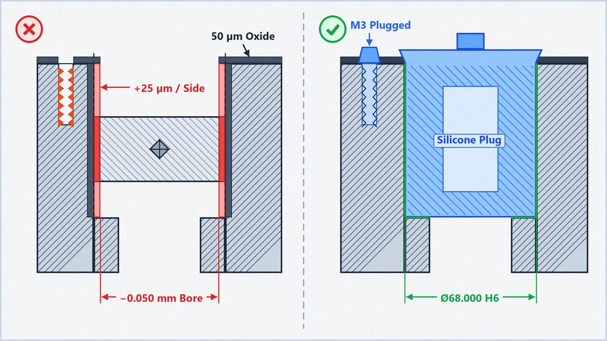
For oscillating Ti-6Al-4V and 17-4PH pins, our precision surface finishing team applies 2–4 µm (0.00008–0.00016 in.) Physical Vapor Deposition (PVD) Diamond-Like Carbon (DLC, μ < 0.10) or ASTM A967 citric passivation. All wearable finishes comply with RoHS/REACH hexavalent-chromium-free rules; compare miniature medical joints in our surgical robot part manufacturing guide.
6. Metrology Verification, CMM Probing & Shop-Floor Troubleshooting
Dimensional verification of a machined exoskeleton robot requires multi-point Coordinate Measuring Machine (CMM) scanning across coaxial bearing bores, pin-to-pin kinematic link lengths, and strain-gauge flexure webs. Relying on two-point vernier calipers misses three-lobed clamping ovality that crushes thin-section harmonic cross-roller bearings; see our CMM precision metrology and GD&T verification guide for scanning protocols.
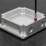
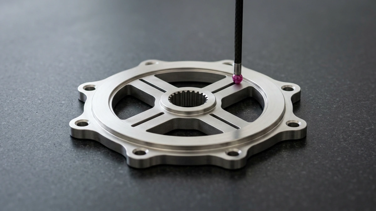
For monolithic 17-4PH H900 joint torque-sensor flexures, we cut 0.50 mm (0.020 in.) overload-stop kerfs using submerged slow Wire EDM on Sodick and Makino machines to hold ±0.005 mm (±0.0002 in.) gap symmetry. As shown in the Zeiss CMM inspection setup below, a vertical ruby stylus probes the top datum face above four radial shear spokes.
| Observed Defect / Symptom | Physical Root Cause | Metrology Detection Method | Shop-Floor Corrective Action | Recommended Application / DFM Prevention Rule |
|---|---|---|---|---|
| Harmonic Drive Torque Ripple & Cyclic Binding | Three-lobed bore cylindricity error (> 0.012 mm) from excessive 3-jaw chuck clamping pressure on thin-wall 7075-T651 housings | Zeiss CMM continuous helical bore scan (≥ 300 points) for cylindricity and 0.010 mm TIR coaxiality | Switch to axial face-clamping or vacuum soft jaws; run a zero-offset spring pass with a fine boring head | Specify ≥ 2.5 mm radial wall thickness around H6/H7 bearing seats and add an axial bolt flange for workholding. |
| Audible Clicking & Free Play in 4-Bar Knee Joints | Cumulative diametral clearance (> 0.060 mm total) across unreamed clevis holes or unmasked anodize acid etching | Pin-gauge go/no-go check (0.001 mm steps) and CMM center-to-center pitch verification (±0.010 mm) | Line-ream opposing clevis ears in one 5-axis setup to H7 (+0.015/-0.000 mm) and plug-mask bores during Type III anodizing | Design double-shear clevis yokes with press-fit bronze or PEEK flanged bushings and ground h6 Ti-6Al-4V pins. |
| Femoral I-Beam Strut Bowing After Unclamping | Asymmetric removal of > 75% billet volume from one face of rolled 7075 plate releasing residual rolling stress | Granite surface plate height-gauge sweep and Zeiss CMM multi-point flatness scan across the 360 mm strut span | Procure stress-relieved 7075-T651 plate; alternate Op-10/Op-20 trochoidal roughing leaving 0.50 mm stock before unclamping | Balance pocket depths symmetrically across the neutral bending axis or design triangular iso-grid ribs on both faces. |
| Strain-Gauge Zero-Point Drift on Torque Flexures | Recast white layer or machining residual stress on 17-4PH H900 shear spokes causing micro-creep under cyclic torque | 2.5D Optical VMS kerf symmetry check, ISO 4287 contact stylus roughness verification (Ra ≤ 0.4 µm), and dead-weight calibration rig | Execute 1 rough cut + 3 skim slow Wire EDM passes on Sodick machines to keep recast layer ≤ 1–2 µm, followed by a 180 °C stress-relief bake | Call out Ra 0.4 µm and 3-skim Wire EDM on all strain-gauge bonding webs and overload stop gaps. |
🔗 Related Robotics & Precision CNC Engineering Guides
- Robotics Prototyping & Precision Manufacturing: Complete Guide for Humanoids, Arms & AMRs
- Surgical Robot Part Manufacturing: Swiss CNC, Wire EDM & Titanium DFM
- Lightweight Metals for CNC Machining: Specific Strength, Stiffness & DFM Guide
- How to Prevent Deformation and Residual Stress in CNC Milling Aluminum
- Press-Fit Tolerance Guide: ISO 286 Interference Calculations & Assembly DFM
7. Technical Engineering FAQ
Harmonic drive and cross-roller bearing seats in a machined exoskeleton robot require ISO 286 H6 or H7 tolerances (+0.019 / -0.000 mm on Ø68 mm bores) and 0.010 mm (0.0004 in.) TIR coaxiality. Non-mating structural webs should default to ISO 2768-mK tolerances to reduce CNC milling cost.
Our machinists prevent thin-wall bowing in 7075-T651 exoskeleton struts by using pre-stretched T651 plate and alternating trochoidal roughing across both faces to leave 0.50 mm (0.020 in.) stock. After unclamping for elastic stress relaxation, we finish-mill 1.5 mm (0.059 in.) iso-grid ribs in contoured soft jaws.
Designers should specify Ti-6Al-4V Grade 5 over 7075-T651 aluminum for compact polycentric knee clevises, pelvic yokes, and pivot pins facing cyclic stress above 500 MPa (72.5 ksi) or sweat exposure. Conversely, 7075-T651 is preferred for long femoral struts where low density maximizes stiffness per gram.
Our in-house CNC machining facility completes bare-machined exoskeleton prototypes in 4 to 8 Business Days, while anodized or PVD-coated assemblies with Zeiss CMM reports take 7 to 12 Business Days. These schedules reflect Ex-Factory Production and Inspection Turnaround, separate from 3 to 5 Days air transit.
Ready to Manufacture High-Precision Exoskeleton Robot Components?
Upload your 3D CAD models (STEP/IGES) and 2D GD&T drawings for a comprehensive DFM review—covering 7075-T651 iso-grid wall stability, H6/H7 bearing bore masking, and Ti-6Al-4V clevis tolerances—from our in-house engineering team.
Upload CAD for Engineering DFM & Quote →