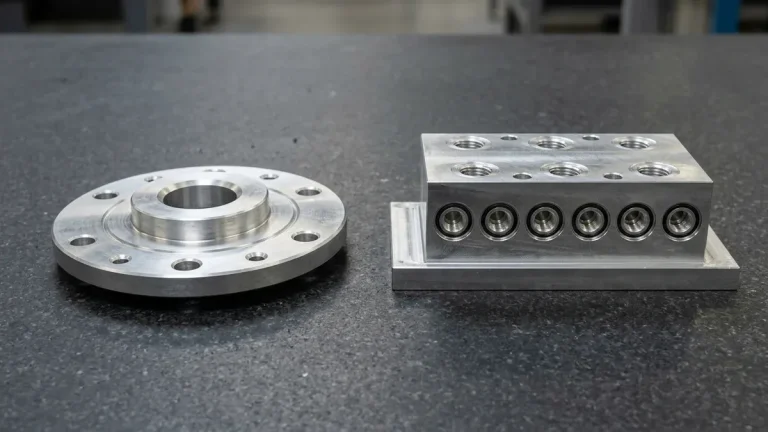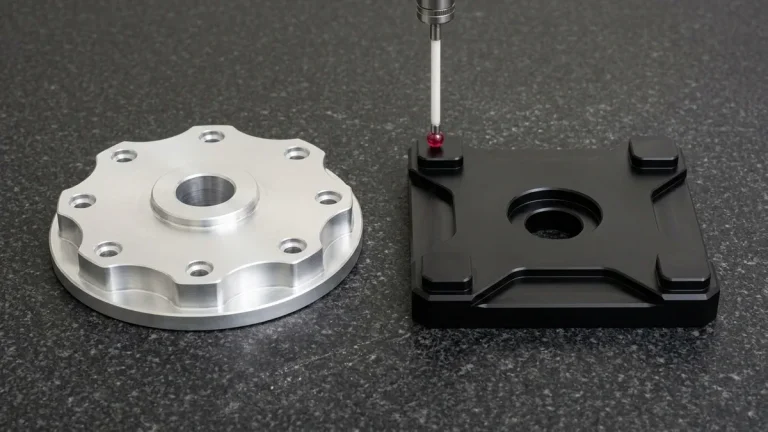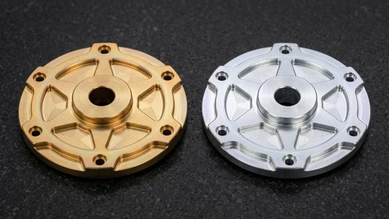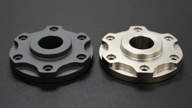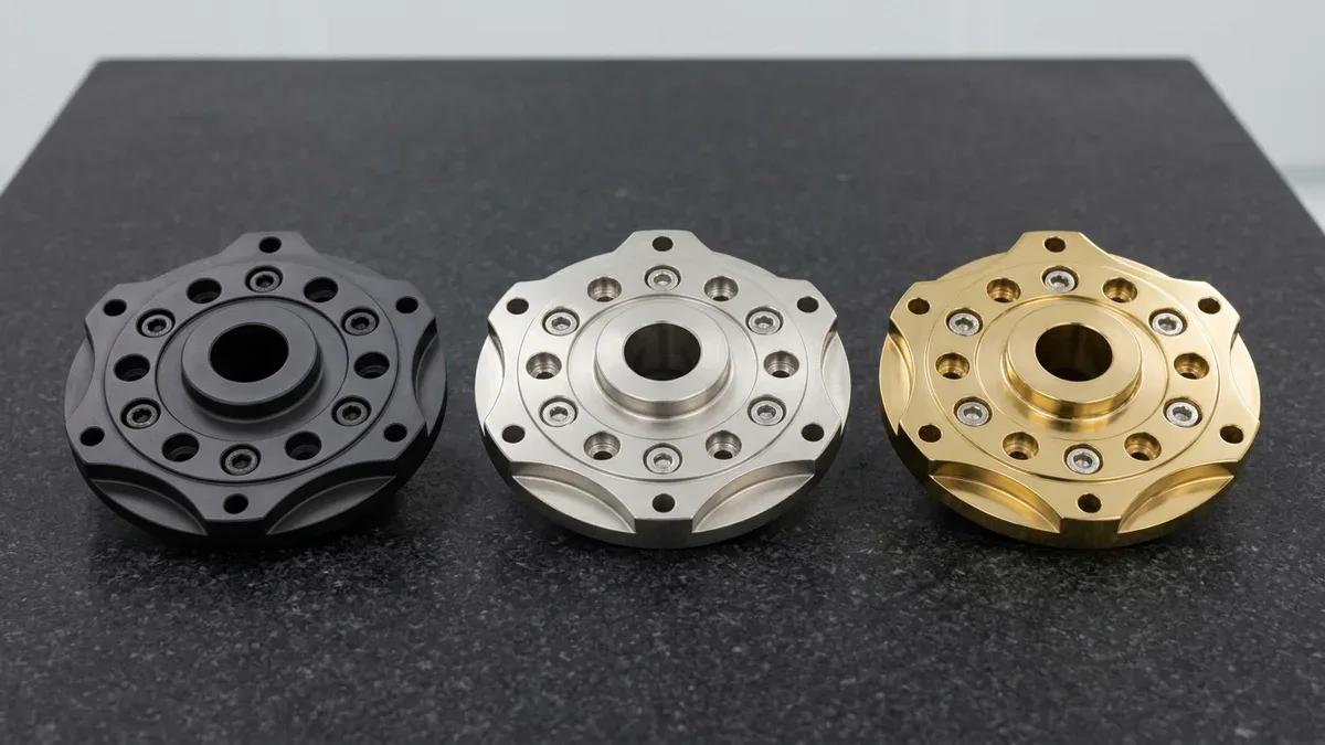
Selecting the optimal types of industrial coatings is a decisive engineering step that prevents premature component failure caused by galvanic corrosion, adhesive galling, abrasive wear, and dielectric breakdown. Across custom Computer Numerical Control (CNC) machined housings, shafts, and sheet metal brackets, engineered surface layers span from 0.25 µm (0.01 mil) conversion films to 120 µm (4.7 mil) polymer barriers.
Unlike cosmetic consumer paints, functional industrial coatings alter surface metallurgy and tribology without sacrificing bulk substrate strength. While electrochemical conversion treatments transform superficial atoms partially inward and partially outward, autocatalytic metallic platings, electrostatic powder coatings, and vacuum thin films deposit 100% additive thickness directly onto external and internal geometries.
At our Shenzhen CNC machining and surface finishing facility, our in-house engineering team evaluates every 3D Computer-Aided Design (CAD) model and 2D drawing to reconcile coating buildup with tight assembly fits. By integrating pre-plate thread allowances, silicone masking, and dry-film metrology, we deliver finished prototypes in 7–12 business days ex-factory before 3–5 business days air transit.
Executive Summary & Engineering Takeaways (BLUF)
- Four Coating Classes: Finishes divide into Conversion Coatings (0.002–75 µm / 0.0001–3.0 mil), Metallic Platings (5–150 µm / 0.2–6.0 mil), Organic Polymer Barriers (15–120 µm / 0.6–4.7 mil), and PVD Thin Films (1.0–4.0 µm / 0.04–0.16 mil).
- Inward vs. Outward Growth: Sulfuric acid anodizing (MIL-A-8625 Type II/III) penetrates 50% inward and builds 50% outward, whereas electroless nickel (ASTM B733), hard chrome (AMS 2460), powder coating, and PVD deposit 100% outward.
- 60° Thread Pitch Multiplier (4× Rule): Normal buildup on 60° thread flanks shifts pitch diameter by Δd2 = 2 × tout ÷ sin(30°) = 4 × tout, requiring masking or pre-plate allowance above 5 µm (0.2 mil).
- Galvanic Compatibility (MIL-STD-889): Dissimilar metal assemblies in marine salt fog must keep anodic potential difference ΔEcorr ≤ 0.15 V (≤ 0.25 V indoors) via zinc-nickel (ASTM B841) or electroless nickel buffer platings.
- Turnaround & Verification: Custom coated prototypes require 7–12 business days ex-factory turnaround (including ISO 2178/2360 DFT and ASTM D3359 Grade 5B checks), separate from 3–5 business days air transit.
Article Engineering Navigation
- 1. Class 1: Electrochemical Conversion Coatings
- 2. Class 2: Metallic Electroplating & Autocatalytic Platings
- 3. Class 3: Organic Polymer & Fluoropolymer Coatings
- 4. Class 4: PVD Vacuum Thin-Film Coatings
- 5. Design for Finishing (DFF): Threads, Radii & Galvanic Rules
- 6. When NOT to Choose: Limitations & Troubleshooting Matrix
- 7. In-House Coating Metrology & Turnaround Standards
- 8. Technical Engineering FAQ
1. Class 1: Electrochemical Conversion Coatings (Anodizing, Chem Film, Black Oxide & Passivation)
Electrochemical and chemical conversion coatings do not deposit a foreign overlay onto the workpiece; instead, they react directly with superficial substrate atoms to form an integral oxide, chromate, or magnetite barrier. Because the converted film shares a continuous metallurgical bond with the base alloy, it exhibits zero risk of interfacial peeling under shear stress.
In high-speed 3-axis and 4-axis CNC milling of aluminum 6061-T6, 6082-T6, and 7075-T651 components—which account for over 80% of prismatic brackets, optical mounts, and fluid manifolds in our shop—anodizing per MIL-A-8625 is the primary conversion treatment. Submerged in an electrolytic sulfuric acid bath, the aluminum workpiece converts into hexagonal porous aluminum oxide (Al2O3).
- Sulfuric Acid Anodizing (MIL-A-8625 Type II): Operated at 18°C–22°C (64°F–72°F), Type II anodizing forms a 5–25 µm (0.2–1.0 mil) film with 50% inward penetration and 50% outward buildup (ΔDOD ≈ +1.0ttotal, ΔDID ≈ −1.0ttotal), passing 336+ hours of ASTM B117 salt spray after sealing.
- Hardcoat Anodizing (MIL-A-8625 Type III): Executed in refrigerated baths at −5°C to 0°C (23°F to 32°F), Type III hardcoat builds a dense 25–75 µm (1.0–3.0 mil) ceramic Al2O3 layer (50% inward / 50% outward) reaching 400–550 HV0.05 microhardness (sliding wear resistance comparable to 60–65 HRC case-hardened steel) and dielectric breakdown above 1,000 V.
- Chromate Conversion / Chem Film (MIL-DTL-5541 Type II, SurTec 650): Trivalent chromium conversion forms a 0.25–1.0 µm (0.01–0.04 mil) conductive film on aluminum chassis (dried strictly ≤ 60°C–65°C / 140°F–149°F to prevent gel dehydration cracking) with contact resistance below 5,000 µΩ/in2 and 168 hours of ASTM B117 protection.
- Black Oxide (MIL-DTL-13924), Passivation (ASTM A967) & Ti Anodizing (AMS 2488): Alkaline black oxide at 140°C (284°F) converts steel into 1.0–2.5 µm (0.04–0.10 mil) magnetite (Fe3O4), whereas stainless steel citric/nitric passivation (nanometer-scale ~0.002 µm Cr2O3) and AMS 2488 Type III titanium anodizing (15–150 nm oxide) impart zero dimensional growth and require zero thread masking.
2. Class 2: Metallic Electroplating & Autocatalytic Coatings (ENP, Hard Chrome & Zinc-Nickel)
When a mechanical component requires surface solderability, sacrificial cathodic protection, extreme sliding wear hardness on ferrous shafts, or uniform corrosion sealing across intricate internal passages, metallic coatings are specified. These finishes deposit a 100% outward metallic layer (ΔDOD = +2.0tcoat, ΔDID = −2.0tcoat) via external electrolysis or autocatalytic chemical reduction.
Unlike electrolytic plating—where electric field lines crowd external corners and starve deep recesses—autocatalytic Electroless Nickel Plating (ENP) per ASTM B733 relies on chemical reduction of nickel ions by sodium hypophosphite. When comparing anodized aluminum and autocatalytic plating specifications, every wetted blind bore and internal thread in an ENP bath receives uniform thickness within ±1.5 µm (±0.00006″).
- Low-, Medium- & High-Phosphorus Electroless Nickel (ASTM B733 / AMS 2404, 48–70 HRC Span): Low-P ENP (1–4% P, 580–650 HV / 54–58 HRC as-plated) maximizes alkaline resistance and solderability; Medium-P ENP (6–9% P, 5–50 µm / 0.2–2.0 mil, 480–520 HV / 48–50 HRC) suits general wear plates; amorphous High-P ENP (10–12% P, 25–75 µm / 1.0–3.0 mil) endures 1,000+ hours of ASTM B117 salt spray and bakes at 400°C (752°F) to 850–1,050 HV (62–70 HRC).
- Electrolytic Hard Chrome (AMS 2460), Zinc (ASTM B633) & Zinc-Nickel (ASTM B841): Hard chrome deposits 25–150 µm (1.0–6.0 mil) at 850–1,100 HV (65–70 HRC, μ = 0.12–0.16) on ground steel shafts; trivalent Zinc (ASTM B633, 5–25 µm / 0.2–1.0 mil) provides 96–240 hours of economical protection, while alkaline Zinc-Nickel (12–15% Ni, 8–15 µm / 0.3–0.6 mil) delivers 720–1,000+ hours of sacrificial salt spray endurance.
3. Class 3: Organic Polymer & Fluoropolymer Barrier Coatings (Powder Coat, E-Coat, 2K Wet Paint & PTFE)
Organic polymer coatings construct a cross-linked macromolecular barrier that physically isolates metallic substrates from moisture, road salt, ultraviolet (UV) radiation, chemical solvents, and gravel impact. In sheet metal enclosures, structural welded frames, and cast housings, polymeric systems provide high film build (15–120 µm / 0.6–4.7 mil) and customizable RAL or Pantone textures.
For laser-cut and CNC press-brake bent 5052-H32 aluminum, SPCC cold-rolled steel, and 304 stainless steel assemblies, custom industrial powder coating and metal surface finishing serve as the primary protective barrier. Dry thermoset resin granules are electrostatically charged at 60–90 kV and sprayed onto grounded parts before thermal cross-linking in convection ovens at 180°C–200°C (356°F–392°F) for 15–20 minutes.
- Thermoset Powder Coating (TGIC Polyester & Epoxy): Applied at 60–120 µm (2.4–4.7 mil); TGIC polyester resists outdoor UV chalking, while epoxy powder maximizes indoor chemical and solvent resistance.
- Cathodic E-Coating & 2K Polyurethane Wet Paint (MIL-PRF-85285): E-coating immerses automotive structural and powertrain components in an epoxy bath for uniform 15–30 µm (0.6–1.2 mil) coverage, while low-bake 2K polyurethane (25–50 µm / 1.0–2.0 mil cured at 60°C–80°C) protects heat-sensitive 7075-T6 parts (which must stay strictly ≤ 100°C–110°C / 212°F–230°F to prevent over-aging strength loss).
- PTFE / Xylan Fluoropolymer Dry-Film Lubricants: Sintered at 15–35 µm (0.6–1.4 mil) to deliver ultra-low dynamic friction (μ = 0.05–0.10) across −195°C to +260°C (−319°F to +500°F) on anti-galling lead screws and subsea studs.
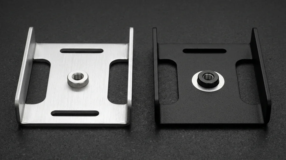
Applying insulating thermoset powder coatings to sheet metal chassis requires localized masking to preserve electrical grounding continuity. The comparison below shows two 2.0 mm (0.079″) 5052-H32 aluminum U-saddle carrier brackets with laser-cut obround slots and knurled self-clinching nuts, contrasting the raw brushed state against a matte black powder-coated finish with a masked bare-aluminum grounding ring.
4. Class 4: Physical Vapor Deposition (PVD) Vacuum Thin Films (TiN, CrN, TiAlN & DLC)
For high-precision mechanical components subject to severe metal-on-metal sliding contact, abrasive wear, or injection molding polymer shear—where dimensional tolerances of ±0.005 mm to ±0.010 mm (±0.0002″ to ±0.0004″) cannot tolerate a 25 µm plating buildup—Physical Vapor Deposition (PVD) vacuum thin films provide ceramic microhardness in a 1.0–4.0 µm (0.04–0.16 mil) layer.
Inside a high-vacuum plasma chamber (10−3 to 10−5 mbar), solid metallic or carbon targets are vaporized via magnetron sputtering or cathodic arc evaporation and reacted with nitrogen or hydrocarbon gases. Ions bombard the biased workpiece, forming an atomically dense thin film that replicates the underlying ground or polished surface roughness (Ra 0.05–0.2 µm / 2–8 µin).
- Titanium Nitride (TiN) & Chromium Nitride (CrN): TiN (1.5–3.0 µm / 0.06–0.12 mil, 2,200–2,400 HV0.05 per ASTM E384) protects 17-4PH H900 stainless and D2 tool-steel wear hubs, while CrN (1.5–4.0 µm / 0.06–0.16 mil, 1,800–2,100 HV0.05) prevents corrosive PVC and elastomer sticking on H13/S136 injection mold cores.
- Titanium Aluminum Nitride (TiAlN / AlTiN), a-C:H DLC & Substrate Tempering Limits: Because standard arc/sputter PVD chambers for TiN, CrN, and TiAlN operate at 350°C–450°C (662°F–842°F), the steel substrate tempering temperature must strictly exceed the PVD deposition temperature (using high-temper D2, H13, or M2 tool steels tempered at 500°C–540°C) to avoid softening; TiAlN (2.0–4.0 µm, 3,000–3,400 HV0.05) resists 800°C oxidation, whereas low-temp PECVD amorphous hydrogenated Diamond-Like Carbon (a-C:H DLC, 1.0–3.5 µm / 0.04–0.14 mil, 2,500–3,500 HV, μ = 0.05–0.12) deposits below 180°C–200°C (356°F–392°F) to protect low-temper tool steels.
| Coating & Standard | Class | Thickness (µm / mil) | Buildup | Hardness | ASTM B117 | Recommended Application / When to Choose |
|---|---|---|---|---|---|---|
| Anodize Type II (MIL-A-8625) | Conversion | 5–25 µm (0.2–1.0 mil) | 50% out | 300–400 HV | 336+ hrs | 6061/7075 CNC brackets and dyed housings. |
| Hardcoat Type III (MIL-A-8625) | Conversion | 25–75 µm (1.0–3.0 mil) | 50% out | 400–550 HV | 336–1,000+ hrs | Sliding aluminum valves and >1,000 V isolation. |
| SurTec 650 (MIL-DTL-5541) | Conversion | 0.25–1.0 µm (0.01–0.04 mil) | <0.5 µm | Base alloy | 168+ hrs | Conductive EMI/RFI aluminum chassis and primers. |
| Black Oxide & Passivation | Conversion | 0.002–2.5 µm | <1.0 µm | Base alloy | 24–240 hrs | Preserves ±0.010 mm (±0.0004″) steel/SS fits. |
| High-P ENP (ASTM B733) | Metallic | 5–75 µm (0.2–3.0 mil) | 100% out | 500–1,050 HV | 1,000+ hrs | Deep blind bores and chemical manifolds. |
| Hard Chrome & Zinc-Nickel | Metallic | 8–150 µm (0.3–6.0 mil) | 100% out | 850–1,100 HV | 720–1,000+ hrs | Hard Cr for rods; Zn-Ni for marine hardware. |
| Powder Coat, E-Coat & PTFE | Polymer | 15–120 µm (0.6–4.7 mil) | 100% out | 2H–4H / μ=0.05 | 500–1,500+ hrs | Sheet metal chassis and dry lubrication. |
| PVD (TiN, CrN, TiAlN, DLC) | Vacuum PVD | 1.0–4.0 µm (0.04–0.16 mil) | 100% out | 1,800–3,500 HV | Base dependent | Hardened tool steels (>45 HRC) and mold cores. |
5. Design for Finishing (DFF): Thread Pitch Diameter Allowance, Edge Radii & Galvanic Compatibility
The single most common cause of rejected assemblies in custom manufacturing occurs when engineers specify tight machining tolerances—such as ±0.010 mm to ±0.020 mm (±0.0004″ to ±0.0008″) bearing bores or ISO 6H/6g threads—without specifying whether those dimensions apply before or after surface coating.
On any external or internal screw thread, coating buildup acts normal (perpendicular) to the angled thread flanks rather than purely radially. For a symmetric thread with flank angle α, a normal film thickness tcoat deposited on both opposing flanks shifts the effective pitch diameter Δd2 according to fundamental trigonometric geometry:
Δd2 = 2 × tout ÷ sin(α ÷ 2)
For standard α = 60° ISO Metric (M) and Unified (UNC/UNF) threads where sin(30°) = 0.50:
- 100% Additive Coatings (ENP, Zinc-Nickel, Powder, PVD where tout = tcoat): Δd2 = 4 × tout = 4 × tcoat per single thread (and Δd2,pair = 8 × tout = 8 × tcoat when both mating internal and external threads are coated).
- 50% Outward Anodizing (MIL-A-8625 Type II/III where tout = 0.5 × tcoat): Δd2 = 4 × tout = 2 × tcoat per single thread (and Δd2,pair = 8 × tout = 4 × tcoat for a coated mated pair).
Worked Example (M8×1.25–6H/6g): When an M8×1.25–6H tapped bore (D2 = 7.188 mm) or mating 6g screw receives tcoat = 15 µm (0.0006″) of high-P ENP, pitch diameter shifts by Δd2 = 4 × 15 µm = 60 µm (0.060 mm / 0.0024″)—shrinking the 6H bore by −0.060 mm and enlarging the 6g screw by +0.060 mm.
Because standard M8×1.25–6g fundamental deviation is only −28 µm (and 6H lower deviation EI is 0 µm), uncompensated plated threads interfere by 32–92 µm and seize solid. Our CAM team therefore masks 6H bores with silicone plugs (or taps oversized 6G limits) and turns external threads to 6e/6f limits above 5 µm (0.2 mil).
In addition to thread geometry, assemblies combining dissimilar metals (such as stainless steel fasteners threaded into aluminum housings or brass fittings mounted on carbon steel manifolds) must satisfy the galvanic potential compatibility rule per MIL-STD-889 to prevent accelerated anodic pitting in the presence of an electrolyte:
ΔEcorr = |Ecathode − Eanode| ≤ 0.15 V (Harsh / Marine) | ≤ 0.25 V (Normal Indoor)
Worked Example: Coupling a bare C3604 brass fitting (−0.40 V) to a 6061-T6 aluminum manifold (−0.75 V) creates a galvanic cell of ΔEcorr = 0.35 V > 0.15 V, pitting the aluminum port. Plating the brass with ASTM B841 Zinc-Nickel (−0.80 V) reduces ΔEcorr to 0.05 V ≤ 0.15 V.
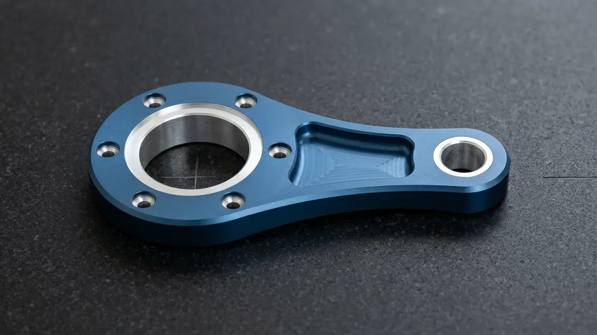
When a component combines an anodized structural body with tight-tolerance ±0.010 mm (±0.0004″) bearing seats, selective silicone masking preserves the raw machined fit. Below is a 3-axis CNC-milled 6061-T6 aluminum pear-shaped twin-bore bearing carrier linkage plate with a deep-blue anodized body, 0.5 mm × 45° (0.020″ × 45°) edge chamfers, and selectively masked bright bearing shoulders.
4-Step Shop-Floor SOP for Pre-Coating Design for Manufacturability (DFM) & Masking Execution
- Break Sharp Corners to R0.3–0.5 mm (0.012″–0.020″): Program a 0.3–0.5 mm × 45° chamfer or radius on all external edges during CNC finishing to prevent organic coating pull-back and anodic corner spalling.
- Apply Pre-Plate CAM Offsets to Unmasked Fits: Shift CNC nominal targets inward by outward buildup tout (e.g., machining an external shaft diameter −0.030 mm / −0.0012″ undersize prior to a 15 µm / 0.0006″ radial high-P ENP deposit).
- Install Silicone Plugs & Masking Halos: Insert 250°C (482°F) tapered silicone plugs into tapped holes (M2.5–M12) and apply die-cut polyester tape disks onto EMI grounding pads before powder coating or hardcoat anodizing.
- Specify Racking Points & Drainage Holes: Call out non-cosmetic internal racking contact locations on the 2D drawing and add Ø3.0–5.0 mm (0.12″–0.20″) weep holes to closed tubes to prevent acid entrapment.
6. When NOT to Choose Specific Coatings: Process Limitations, Trade-Offs & Defect Troubleshooting
Every industrial coating involves metallurgic, thermal, or geometric trade-offs. Selecting a high-hardness or thick barrier coating without accounting for substrate alloy chemistry, tempering limits, or cyclic bending fatigue can degrade structural reliability rather than improve it.
- When NOT to Choose MIL-A-8625 Type III Hardcoat Anodizing: Avoid thick Type III hardcoat (>50 µm / 2.0 mil) on 7075-T6 aerospace links under high-cycle bending fatigue (cuts fatigue life by 20%–35%) or on high-silicon die-cast alloys (ADC12 / A380 with >8% Si).
- When NOT to Choose Electrolytic Hard Chrome or Acid Electroplating: Never apply electrolytic hard chrome (AMS 2460) or acid zinc (ASTM B633) to steels ≥ 31 HRC (≥1,000 MPa / 145 ksi) without a 190°C ± 14°C (375°F ± 25°F) hydrogen embrittlement relief bake within 3 hours per ASTM B850; avoid electrolytic chrome in deep bores (L/D > 2:1).
- When NOT to Choose Powder Coating & High-Temp PVD Thin Films: Never bake 180°C–200°C powder coatings on 7075-T6/T651 (must stay ≤ 100°C–110°C to avoid over-aging); never deposit 180°C–450°C PVD films onto steels whose tempering temperature is lower than the PVD chamber temperature or onto soft substrates below 45 HRC under concentrated Hertzian contact stress (egg-shell spallation).
| Defect / Failure Mode | Class | Root Mechanism | Recommended Corrective Action / When to Choose Alternative |
|---|---|---|---|
| Corner Voiding & Edge Pull-Back | Anodize / Powder | Oxide splits at 90° edges; polymer pulls away via surface tension. | Machine R0.4–0.8 mm (0.016″–0.031″) corner radii before finishing. |
| Thread Seizure & Interference | ENP / Zn-Ni / Type III | 60° flank magnifies outward buildup by 4× on pitch diameter (Δd2 = 4 × tout). | Plug M8 × 1.25 — 6H bores with silicone maskers or tap oversized 6G limits. |
| Hydrogen Embrittlement | Hard Cr / Acid Zn | Atomic hydrogen diffuses into steel (≥31 HRC) grain boundaries. | Bake at 190°C ± 14°C (375°F ± 25°F) within 3 hours (ASTM B850) or use PVD. |
| Faraday Bore Starvation | Electroplate / Powder | Electric field crowds outer corners and starves cavities (L/D > 1.5:1). | Choose autocatalytic Electroless Nickel (ASTM B733) or E-Coating. |
| PVD Egg-Shell & Softening | PVD TiN / CrN / DLC | Soft base (<45 HRC) deforms or PVD heat (180–450°C) exceeds temper. | Use high-temper steels (52–62 HRC, temper >450°C) or <180°C DLC. |
7. In-House Coating Metrology: DFT Thickness, Cross-Hatch Adhesion & Salt Spray Verification
Delivering zero-defect coated components requires quantitative inspection of both the surface layer and the post-coated geometric tolerances. In our Shenzhen 20°C ± 1°C (68°F ± 1.8°F) climate-controlled metrology laboratory, every batch of finished prototypes and production parts undergoes standardized verification tailored to the substrate and coating class before packaging.
To prevent damage to delicate thin-walled sheet metal stampings or flexible polymer housings, our quality team strictly separates non-contact and gauge-based surface checks from rigid metal CMM inspection. Explore our full suite of industrial surface finishing and coating capabilities integrated with our in-house quality lab:
- Dry-Film Thickness (DFT) Metrology (ISO 2178 / ISO 2360): Non-magnetic coatings on ferromagnetic steel are measured via magnetic-induction probes per ISO 2178, while anodic oxides and organic powder coatings on aluminum are verified via non-destructive eddy-current probes per ISO 2360 to ±1.0 µm (±0.00004″) repeatability.
- Cross-Hatch Adhesion (ASTM D3359) & Salt Spray (ASTM B117): Organic polymer films are scribed in a 6 × 6 grid (1.0 mm or 2.0 mm spacing) and tape-tested to Grade 5B (0% flaking), while witness panels undergo 5% NaCl salt spray at 35°C (95°F) from 96 to 1,000+ hours.
- Roughness, Hardness, CMM & Turnaround: We verify roughness via stylus profilometers (ISO 4287), hardness via Rockwell/Vickers testers (ASTM E18/E384), and rigid metal datums/threads via Zeiss Contura bridge Coordinate Measuring Machine (CMM) (available upon request), 2.5D optical Vision Measuring Systems (VMS), and GO/NO-GO gauges. Raw CNC prototypes ship in 4–8 business days ex-factory, and coated prototypes in 7–12 business days ex-factory (7–30 business days for production), separate from 3–5 business days express air transit.
🔗 Related Surface Finishing & Coating Engineering Guides
8. Technical Engineering FAQ
Additive coatings like electroless nickel and powder coating build 100% outward, shifting a 60° screw thread pitch diameter by four times outward film thickness (Δd₂ = 4 × t). Consequently, films above 5 µm (0.2 mil) require pre-plate undersized 6e/6f threads, oversized 6G/6H+ taps, or silicone plugs.
Specify high-phosphorus electroless nickel (ASTM B733, 10–12% P) when parts require electrical conductivity, solderability, or ±1.5 µm (±0.00006″) uniform thickness inside deep blind bores. Choose MIL-A-8625 Type III hardcoat anodizing on 6061-T6 aluminum when applications demand dielectric insulation above 1,000 V and sliding ceramic wear resistance.
Physical vapor deposition films such as Diamond-Like Carbon (DLC) measure only 1.0 to 4.0 µm (0.04 to 0.16 mil) thick despite reaching 2,500 to 3,500 HV microhardness. Applying ultra-thin ceramic films over soft substrates below 45 HRC causes egg-shell indentation and spallation under concentrated Hertzian contact stresses.
Our Shenzhen facility completes raw CNC-machined prototypes in 4 to 8 business days, while parts requiring anodizing, electroless nickel, powder coating, or PVD take 7 to 12 business days ex-factory. All ex-factory production and metrology turnarounds exclude 3 to 5 business days of international express air transit.
Ready to Optimize Your Custom Parts for Precision Manufacturing?
Upload your 3D CAD models and 2D engineering drawings for a comprehensive Design for Finishing review covering pre-plate thread allowances, selective masking zones, and substrate-coating compatibility. Our in-house CNC machining, sheet metal, and surface treatment engineers ensure your finished components meet exact dimensional and corrosion specifications on the first build.
Request a Technical DFM & Custom Quote →