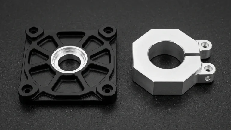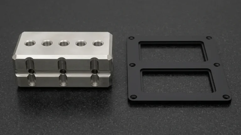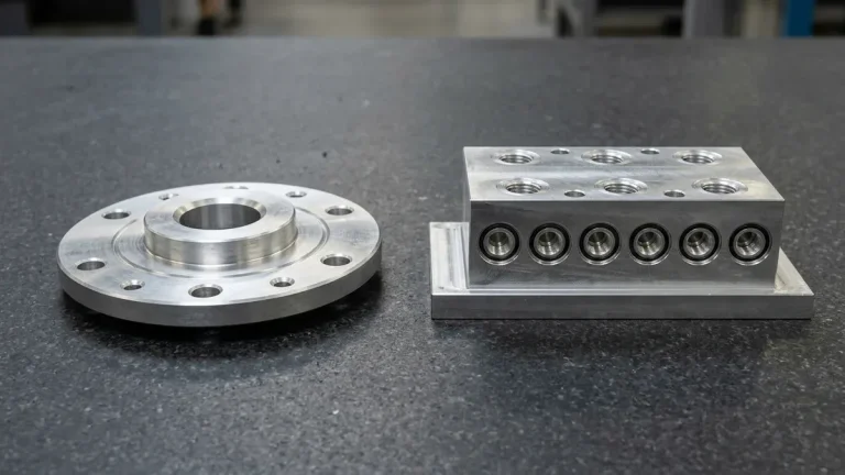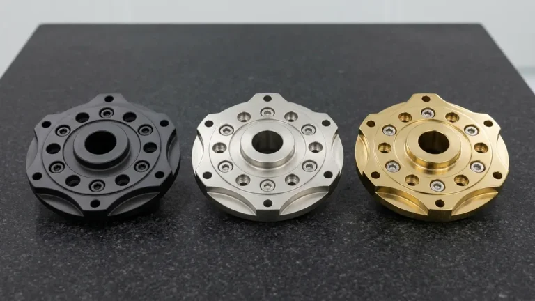
Knowing how to create a prototype that transitions smoothly from 3D CAD into production separates fast hardware teams from programs stalled by tooling rework. Rather than treating prototyping as a standalone 3D-printing step, product development follows four gates: Proof of Concept (PoC), Engineering Validation (EVT), Design Validation (DVT), and Production Validation (PVT).
Across multi-component mechanical assemblies, individual part tolerances compound geometrically across every mating joint, bearing bore, and elastomeric seal interface. At our in-house precision CNC machining, additive manufacturing, sheet metal, and rapid tooling facility, our engineering team combines parallel multi-process fabrication with up-front Design for Manufacturability (DFM) reviews to eliminate interference failures before cutting production molds.
Executive Summary & Engineering Takeaways (BLUF)
- Stage-Gate Fidelity Separation: Decouple early “looks-like” ergonomic models (SLA/FDM, ±0.15–0.20 mm) from “works-like” structural EVT prototypes (3-axis and 4-axis CNC billet machining, ±0.010–0.020 mm) before converging both into DVT/PVT pre-production builds.
- Assembly Rolled Throughput Yield (RTY): In a 12-interface assembly, a 95.0% per-feature pass rate drops first-build assembly yield to 0.95¹² = 54.0%; enforcing 3-2-1 GD&T datum synchronization at 99.5% interface capability restores first-build yield to 94.2%.
- The 50× Hard-Tooling Rework Penalty: Resolving a 0.25 mm (0.010 in) boss interference during a 4–8 business day CNC or MJF prototype sprint avoids 10–18 business days of EDM welding and re-machining on pre-hardened P20 (28–34 HRC) or hardened H13 (48–52 HRC) injection molds (a 15×–50× rework cost multiplier).
- Parallel Multi-Process Compression: Simultaneously machining load-bearing 6061-T6 / 7075-T651 brackets on 3/4-axis VMCs while printing PA12 nylon manifolds via MJF and bending 5052-H32 sheet metal chassis cuts multi-part build cycles by 45%–60%.
- Ex-Factory vs. Air Transit Separation: Standard ex-factory fabrication and inspection spans 4–8 business days for as-machined CNC, sheet metal, and 3D prints (7–12 business days with finishing or vacuum casting; 18–35 business days for rapid tooling), plus 3–5 business days DHL/FedEx air transit.
Article Engineering Navigation
- 1. How Do PoC, EVT, DVT, and PVT Stage-Gate Exit Criteria Govern Hardware Prototyping?
- 2. Why Does Multi-Part Assembly Rolled Throughput Yield (RTY) Collapse Without Datum Synchronization?
- 3. What Is the 7-Step Engineering Blueprint for Creating a Physical Prototype from 3D CAD?
- 4. How Does Iterative Rev A to Rev B DFM Refinement Prevent 50× Tooling Rework?
- 5. How Do Metrology Verification, IP Security, and Ex-Factory Lead Times De-Risk Launch?
- 6. Technical Engineering FAQ
1. How Do PoC, EVT, DVT, and PVT Stage-Gate Exit Criteria Govern Hardware Prototyping?
Leading hardware organizations structure physical product development around four sequential validation gates: Proof of Concept (PoC), Engineering Validation Testing (EVT), Design Validation Testing (DVT), and Production Validation Testing (PVT). Rather than building full-fidelity assemblies on Day 1, experienced engineers separate early prototypes into parallel “looks-like” industrial design models and “works-like” electro-mechanical test rigs.
Splitting aesthetic ergonomics from structural thermal and load testing during PoC and early EVT prevents minor industrial design shell tweaks from stalling core drivetrain or PCB development. Once both tracks pass independent verification, DVT merges production-intent materials, tight geometric tolerances, and cosmetic surface treatments into unified assemblies for environmental and drop qualification.
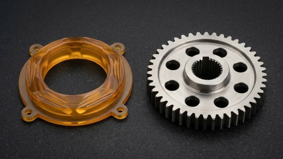
Below, two distinct stage-gate prototype components illustrate this dual-track separation on black granite: an industrial photopolymer 3D-printed and clear-coated translucent amber optical light-guide ring with four mounting tabs and faceted ribs (left) alongside a 4-axis CNC-machined 17-4PH stainless steel spur gear and splined hub carrier featuring eight circular lightening holes (right).
For a process-by-process physics breakdown comparing additive polymers, subtractive milling, silicone casting, and bridge tooling, consult our pillar rapid prototyping technologies guide. Table 1 below defines the quantitative engineering exit criteria, target batch volumes, tolerance budgets, and verification requirements that govern each hardware development gate.
| Validation Gate | Fidelity Track & Typical Batch | Primary Fabrication Processes | Critical Tolerance Budget | Mandatory Engineering Exit Criteria to Advance |
|---|---|---|---|---|
| 1. Proof of Concept (PoC) | Isolated “Looks-Like” or Breadboard Rig (1–5 units) | SLA / FDM / SLS 3D Printing, Basic 3-Axis CNC Delrin/6061 Plates | ±0.15 mm to ±0.25 mm (±0.006 in to ±0.010 in) | Core kinematic mechanism functions on benchtop; ergonomic envelope approved by industrial design. |
| 2. Engineering Validation (EVT) | “Works-Like” Functional Engineering Build (5–25 units) | 3-Axis & 4-Axis CNC Milling/Turning, MJF PA12, Laser/Bent Sheet Metal | ISO 2768-mK general; ±0.010–0.020 mm (±0.0004–0.0008 in) fits | 100% PCB/harness fit; structural safety factor FS ≥ 1.5; steady-state thermal rise within ΔT target. |
| 3. Design Validation (DVT) | Merged Looks-Like + Works-Like Build (20–100 units) | Multi-Axis CNC + Anodizing/Plating, Polyurethane Vacuum Casting, 7075 Bridge Molds | ±0.010 mm CNC datums; ±0.10–0.15 mm molded/cast contours | Passes -40°C to +85°C thermal cycling, IP67/IP68 pressure-decay seal test, drop/vibration, and design freeze. |
| 4. Production Validation (PVT) | Production-Intent Pilot Run (100–2,000+ units) | P20/NAK80 Rapid Injection Tooling, Multi-Fixture CNC Pallet Cells, Stamping | Full FAI Form 1/2/3 compliance; CTQ capability Cpk ≥ 1.33 | Assembly line takt time verified; first-pass assembly yield RTY ≥ 95%; zero unresolved tooling DFM actions. |
2. Why Does Multi-Part Assembly Rolled Throughput Yield (RTY) Collapse Without Datum Synchronization?
A common pitfall when learning how to create a prototype is inspecting each component in isolation without modeling how tolerances stack up across mating interfaces. A robotic actuator or medical pump contains dozens of coupled fits—bearing pockets, stepped shafts, dowel pins, sheet metal brackets, and molded ducts—that must assemble without binding.
In statistical manufacturing engineering, the probability that a complete multi-part prototype assembly fits together on the first bench build without hand-filing or re-drilling is governed by Rolled Throughput Yield (RTY). When an assembly contains n independent critical mating interfaces, each with an individual dimensional pass probability Yi, total assembly yield multiplies exponentially:
RTYassembly = Y₁ × Y₂ × … × Yn = (Yinterface)n | Pinterference = 1 − RTYassembly
📐 Worked Calculation: 12-Interface Prototype Sub-Assembly First-Build Yield (RTY)
Evaluating first-article bench assembly success across an electro-mechanical prototype module containing n = 12 critical mating interfaces (two bearing bores, one stepped shaft journal, four dowel pin holes, three fastener patterns, and two manifold port seals):
- Uncoordinated Multi-Vendor Build (Yi = 95.0% per interface): Even when 19 out of 20 individual features are within print, overall assembly yield drops to RTY = 0.95¹² = 0.5404 (54.0%)—meaning a 46.0% probability that at least one interface binds or misaligns during EVT assembly.
- Synchronized Single-Source DFM Build (Yi = 99.5% per interface): Aligning datum reference frames and verifying mating fits prior to shipment raises per-interface yield to 99.5%, lifting first-build assembly yield to RTY = 0.995¹² = 0.9416 (94.2%).
- Tolerance Stack-Up & Fit Delegation: Worst-case versus Root-Sum-Square (RSS) stack-up equations are derived in our CNC machining tolerances guide, while ISO 286-2 H7/p6 press-fit interference formulas are detailed in our press-fit tolerance engineering guide.
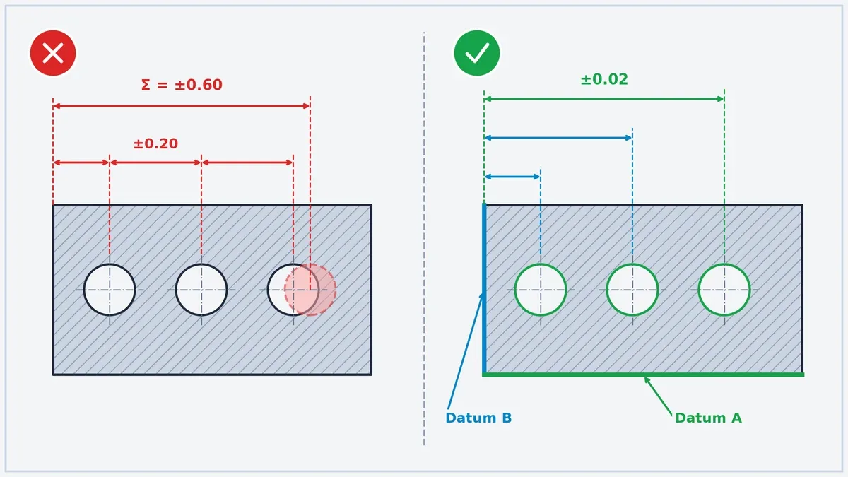
As shown in the 2D CAD schematic below, chain-dimensioning hole-to-hole steps allows individual ±0.20 mm linear tolerances to accumulate into a Σ = ±0.60 mm positional stack-up error at the final bore (left). Anchoring all hole positions to perpendicular Datum A and Datum B baseline edges holds positional accuracy within ±0.02 mm (right).
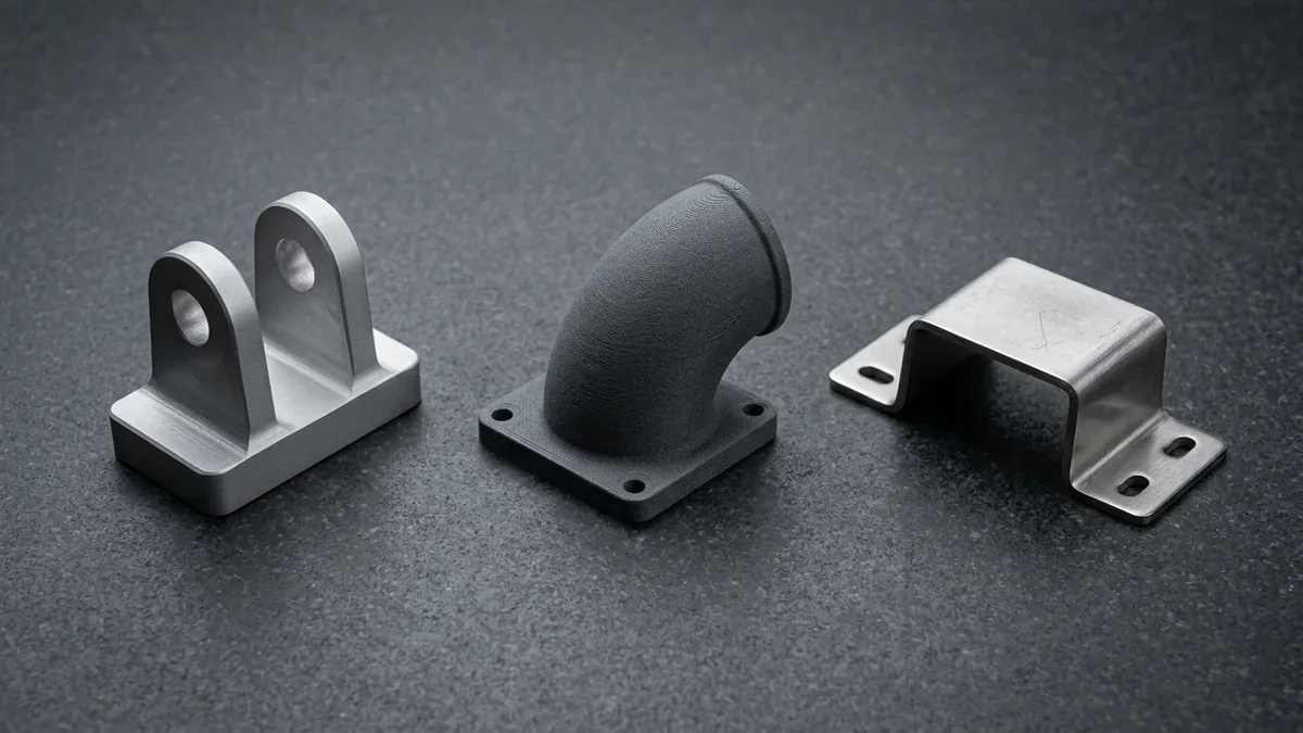
To prevent multi-vendor datum drift, our project engineers fabricate coupled sub-assemblies concurrently and verify mating fits before shipment. Below, three multi-process prototype parts—a CNC-milled 7075-T651 aluminum double-ear clevis fork yoke, an MJF PA12 nylon 90-degree flanged air-intake elbow, and a 2.5 mm 304 stainless steel hat-channel omega bracket—rest on black granite.
3. What Is the 7-Step Engineering Blueprint for Creating a Physical Prototype from 3D CAD?
Moving from a digital 3D assembly to verified physical hardware without mid-build holds requires standardizing file exports, raw material tempers, datum callouts, and surface coating allowances before releasing files to the shop floor. Following our seven-step engineering execution sequence eliminates quoting ambiguity and prevents preventable machining or molding defects.
- Export Native Parametric 3D Solid CAD (STEP AP242 / IGES): Always export solid boundary-representation models in STEP (.stp / .step) format rather than faceted triangle meshes for subtractive CNC milling, turning, sheet metal, and tooling so CAM software extracts true cylindrical bore axes; when exporting STL / 3MF meshes for industrial 3D printing, set chordal deviation to ≤ 0.010 mm (0.0004 in) as detailed in our CAD file formats for CNC machining guide.
- Pair Material Grades & Stress-Relieved Tempers to Functional Loads: Specify 6061-T6 aluminum for general structural brackets, pre-stretched 7075-T651 plate for high-load aerospace clevises, ductile 5052-H32 for bent sheet metal chassis, and POM-C (Delrin) or PEEK for low-friction bearing slides. To prevent thin-wall warpage when hogging out asymmetric aluminum pockets, apply the intermediate stress-relief protocols in our aluminum machining dimensional stability guide.
- Establish a 3-2-1 Datum Reference Frame & 2D GD&T Callouts: Accompany every 3D STEP model with a 2D PDF drawing defining primary plane Datum A, secondary line Datum B, and tertiary point Datum C per ASME Y14.5 / ISO 1101. Assign ISO 2768-mK to non-critical outer contours and restrict tight ±0.010–0.020 mm (±0.0004–0.0008 in) tolerances to functional bearing bores, dowel holes, and sealing faces per our engineering drawing overview guide.
- Partition Multi-Process BOM Sub-Assemblies & Interface Clearances: Divide the bill of materials (BOM) by process physics—assigning load-bearing frames to CNC milling, complex internal ducts to SLS/MJF, and sheet enclosures to laser/brake forming—while adding 0.15–0.25 mm (0.006–0.010 in) perimeter assembly clearance between mating polymer and metal housings. For single-feature pocket relief and sheet-metal bend-zone formulas, consult our guides on sharp internal corners in CNC machining and precision sheet metal forming.
- Map Surface Coating Masking Zones on 2D Assembly Drawings: Highlight critical bearing journals, ground chassis bonding pads, and fine tapped holes with color-coded cross-hatching on the 2D PDF drawing so our finishing line installs silicone plugs or EPDM caps prior to tank immersion. Full oxide growth and pre-machining bore compensation tables are maintained in our aluminum anodizing specification guide.
- Execute Parallel Fabrication with In-Process Spindle Probing: Schedule high-speed 3-axis and 4-axis VMC milling (which handles 75%–85%+ of prismatic metal prototypes), CNC turning, SLA/SLS/MJF printing, and polyurethane vacuum casting in parallel rather than sequentially, using on-machine touch probes to lock OP1-to-OP2 datum alignment within ≤ 0.010 mm.
- Conduct Process-Matched Metrology & Bench Fit-Up Verification: Verify rigid CNC-machined metal datums via calibrated plug gauges and bridge CMM probing, inspect polymer 3D-printed or vacuum-cast housings via non-contact 2.5D optical vision systems, and perform physical fastener/bearing trial assembly prior to ex-factory release.
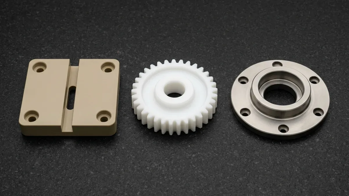
Selecting engineering polymers and specialty metals in Step 2 allows EVT builds to replicate production thermal, dielectric, and tribological behavior. Below, three precision CNC-machined prototypes—a natural khaki-beige PEEK thermal insulator block with four counterbored corner holes and a central through-slot, a white POM-C acetal spur gear, and a Ti-6Al-4V titanium flanged bearing housing ring—rest on black granite.
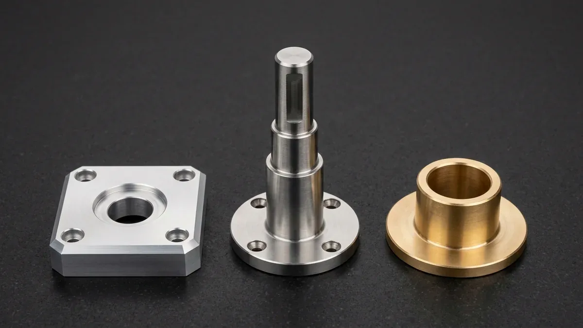
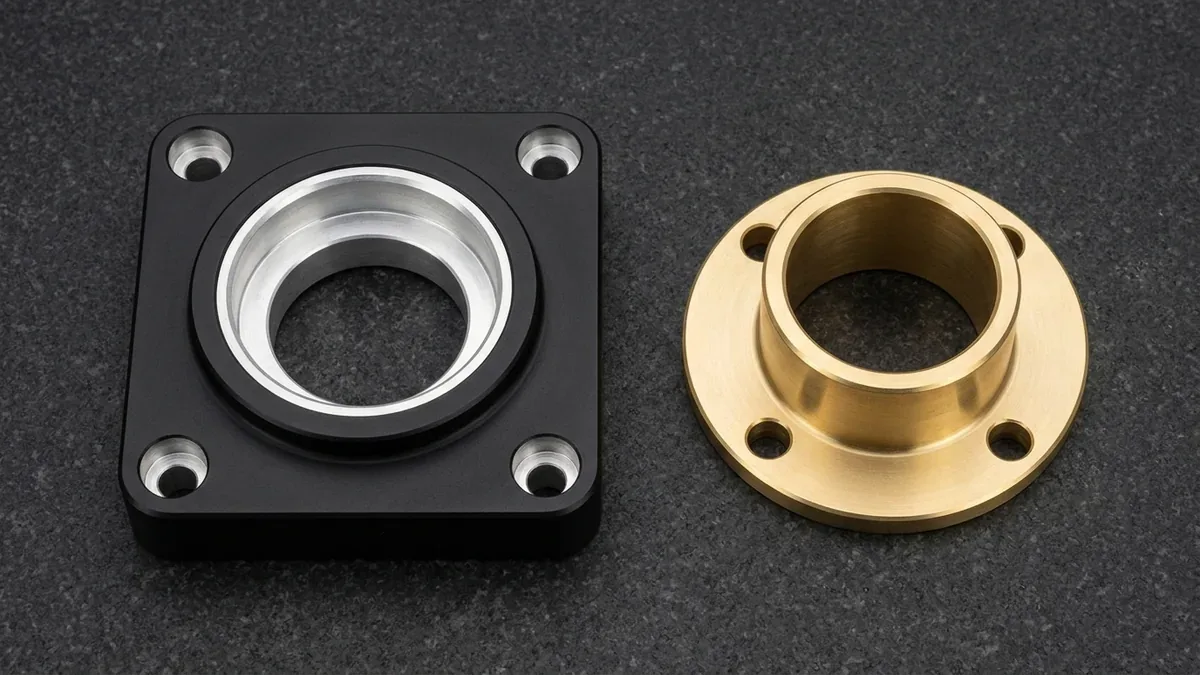
Similarly, executing Step 5 requires masking tight-tolerance bearing fits during anodizing so oxide growth never causes press-fit seizure. Below, a 3-axis CNC-milled 6061-T6 matte-black anodized aluminum bearing mount plate featuring a bright silver bare-aluminum central stepped bearing pocket preserved by silicone masking sits beside its mating CNC-turned C3604 golden brass flanged sleeve bushing.
4. How Does Iterative Rev A to Rev B DFM Refinement Prevent 50× Tooling Rework?
The primary economic return of physical prototyping is discovering structural resonance, thermal throttling, or assembly tolerance stack-up errors while changes still take hours in CAD rather than weeks in hardened steel. In hardware manufacturing economics, the Rule of 10 dictates that engineering change order (ECO) costs escalate by an order of magnitude at each downstream stage.
Modifying a mounting boss diameter or machining weight-relieved stiffening ribs and adjustment slots between Rev A and Rev B during an EVT CNC machining sprint requires only a CAM toolpath update and a 4 to 8 business day turnaround. Conversely, discovering that same defect after cutting a multi-cavity rapid injection molding tool requires laser mold welding and Sinker EDM re-burning.
Tparallel = max(TCNC, T3DP, TSheetMetal) = 4–8 Days vs. Ttooling-rework = TT1 (18–35d) + ΔTEDM (10–18d)
📐 Worked Calculation: Parallel Prototype Iteration Window vs. Hard-Tooling ECO Rework Penalty
Comparing schedule impact and engineering rework cost multiplier when resolving a 0.30 mm (0.012 in) servo mount deflection and boss misalignment across two validation strategies:
- Two-Build EVT CNC Iteration (Rev A → Rev B): Fabricating Rev A in 6061-T6 aluminum takes 5 business days; bench testing reveals web flexing under peak torque; machining the ribbed Rev B iteration takes another 5 business days (10 business days total at 1.0× baseline prototype cost).
- Premature Bridge Tooling Rework (Skipping Billet EVT): Cutting a P20 steel mold requires 22 business days to T1 samples; correcting the interference via laser build-up welding, CNC re-milling, EDM re-sinking, and T2 trial molding adds 12 to 18 business days and incurs a 15× to 50× engineering rework cost penalty.
- Cubic Bending Stiffness Gain (h³): Increasing local rib height from a 3.0 mm flat plate web (Rev A) to a 9.0 mm pocketed cruciform stiffening rib profile (Rev B) multiplies local flexural moment of inertia (I = b × h³ / 12) by (9.0 / 3.0)³ = 27× while reducing overall plate mass via four corner weight-relief pockets.
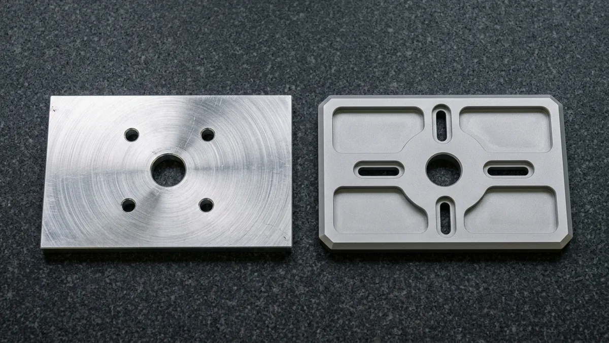
Below, two CNC-machined 6061-T6 aluminum servo motor mounting plate revisions rest on black granite: the initial as-milled Rev A plate (left) uses an un-ribbed flat plate with fixed mounting holes, whereas the clear-anodized stiffened Rev B iteration (right) integrates four filleted weight-relief pockets, orthogonal cruciform stiffening ribs with slotted mounting holes, and a chamfered perimeter.
When transitioning from machined or 3D-printed DVT prototypes to bridge injection tooling, thick uncored screw bosses accumulate thermal mass over nominal wall thickness t, causing internal shrinkage voids and cosmetic Sink Mark depressions (left). Redesigning the boss with a deep cored bore, 0.6t wall thickness, smooth R = 0.25t root fillets, and gusset ribs eliminates sink defects (right).
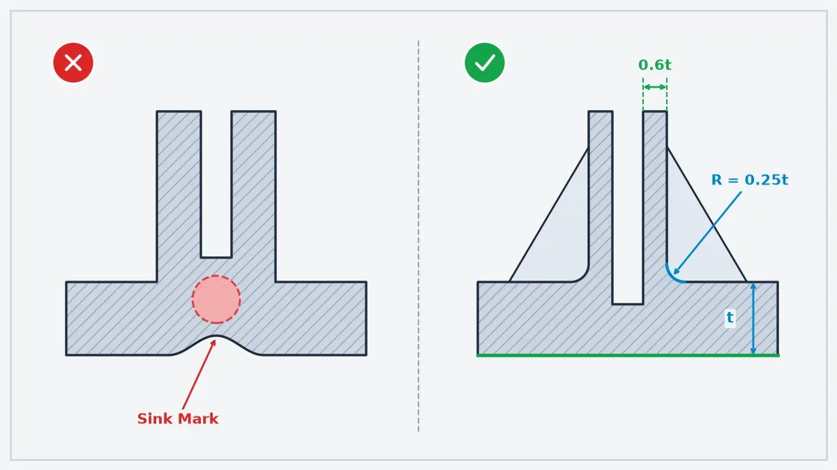
Table 2 summarizes the five most common prototype failure modes uncovered during EVT and DVT bench testing, alongside their physical root causes and the exact Rev A to Rev B CAD modifications our engineering team recommends prior to freezing tooling.
| Observed Assembly Failure Mode | Physical & Mechanical Root Cause | Rev A → Rev B CAD & Assembly Corrective Action | Quantitative Verification Target |
|---|---|---|---|
| Mating PCB or square block rocks inside CNC pocket | Rotating cylindrical end mill leaves natural internal corner radius that interferes with 90° mating corners | Add diagonal dog-bone or T-bone corner relief cuts (R ≥ 0.55 × cutter diameter D) or chamfer the mating board corners | 100% flush seating on Datum A with 0.02 mm feeler gauge check |
| Polymer gear or bushing binds on metal shaft during thermal cycling | Coefficient of thermal expansion (CTE) mismatch (ΔL = α × L₀ × ΔT) between POM/PA12 (α ≈ 90–110 × 10⁻⁶/K) and 304 SS (17 × 10⁻⁶/K) across −40°C to +85°C | Switch to glass-filled PEEK or bronze-sleeved bushings, or expand radial running clearance from H7/g6 to H8/f7 to absorb thermal growth | Zero torque spike across −40°C to +85°C DVT environmental chamber soak |
| Multi-bolt housing cover fasteners bind or fail to align at assembly | Tight clearance holes combined with chain-dimensioned hole patterns violate ASME Y14.5 positional tolerance budgets—floating-fastener (T = H − F) for dual clearance holes or fixed-fastener (T = (H − F) / 2) for tapped holes | Locate cover via two precision dowel pins (one round, one diamond relief pin) and size screw clearance bores to ISO 273 medium series (e.g., ⌀4.5 mm for M4) | Drop-in gauge pin check & 100% first-time bolt thread engagement |
| Vacuum-cast or molded plastic boss cracks during screw torquing | Self-tapping screws generate excessive hoop stress in thin unreinforced polyurethane or ABS boss walls | Replace self-tapping plastic bosses with knurled C3604 brass heat-set or cast-in-place threaded inserts with boss OD ≥ 2.2 × insert OD | Survives ≥ 50 assembly/disassembly cycles at rated M3/M4 torque |
| IP67 enclosure flange leaks or sheet-metal cover bows over O-ring | Excessive bolt spacing allows flange bowing between screws, or PEM standoff backside swage protrusion prevents flat metal-to-metal gland seating | Size AS568 O-ring gland depth for 20%–25% cross-section squeeze (75%–80% gland fill) and machine ⌀8.0 × 0.5 mm clearance counterbores opposite PEM heads | Passes 1.0 meter / 30-minute IP67 pressure-decay & immersion test |
5. How Do Metrology Verification, IP Security, and Ex-Factory Lead Times De-Risk Launch?
Delivering reliable prototypes requires matching the inspection instrument to the physical stiffness and tolerance regime of each manufacturing process. Our 20°C ± 1°C (68°F ± 1.8°F) climate-controlled metrology laboratory applies distinct verification protocols to rigid machined metals, flexible polymers, and formed sheet metal.
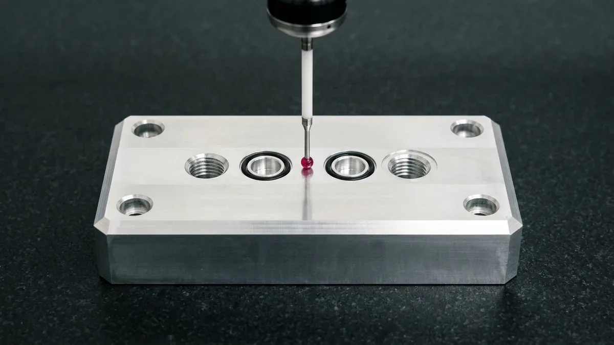
For rigid CNC-machined metal components and post-machined DMLS datums, bridge Coordinate Measuring Machines (CMM, available upon request) use a spherical ruby stylus to verify linear bore and datum step tolerances down to ±0.005–0.010 mm (±0.0002–0.0004 in) and geometric flatness, perpendicularity, and true position within 0.005–0.015 mm (0.0002–0.0006 in) tolerance zones, supplemented by Mitutoyo 3-point internal bore micrometers and ISO 1502 Go/No-Go thread plug gauges.
Conversely, because polymer 3D-printed parts (SLA/SLS/MJF) and elastomeric castings exhibit elastic compliance under tactile probe pressure, our quality engineers inspect polymer prototypes using non-contact 2.5D Optical Vision Measurement Systems (VMS). Formed sheet metal brackets are verified via granite squareness gauges, radius gauges, pin gauges, and physical mating assembly fit-up checks.
Ballooned drawing protocols and dimensional reporting formats are detailed in our First Article Inspection (FAI) guide and CMM metrology verification guide. Below, a vertical ceramic stylus with a spherical ruby probe ball contacts the top horizontal datum face of a CNC-machined 6061-T6 aluminum hydraulic valve manifold block resting flat on black granite.
Intellectual Property (IP) Protection & Ex-Factory Lead Time Planning
Because early EVT and DVT builds embody confidential product architectures, our facility enforces strict intellectual property safeguards alongside predictable production scheduling. Every hardware program is protected by three operational controls and clearly separated ex-factory versus air-transit lead time tiers:
- Binding Mutual NDA & Isolated CAM Network: We execute mutual Non-Disclosure Agreements (NDAs) prior to CAD upload, process STEP/IGES files on segmented internal engineering workstations, and mechanically crush setup scrap or superseded Rev A test parts.
- 24-Hour Engineering DFM Review & Quotation: Every RFQ receives a line-by-line manufacturability audit and custom quote Within 24 Hours (24–48 Hours for multi-cavity bridge molds or large multi-process BOMs).
- 4 to 8 Business Days Ex-Factory (As-Machined CNC, Sheet Metal & SLA/SLS/MJF): Includes raw mill test report (MTR) verification, 3/4/5-axis machining or additive build, deburring, and dimensional QC verification.
- 7 to 12 Business Days Ex-Factory (Secondary Surface Finishing & Vacuum Casting): Covers MIL-A-8625 Type II/III anodizing, chromate conversion, electropolishing, powder coating, or RTV silicone mold fabrication plus 10–50 cast polyurethane units.
- 18 to 35 Business Days Ex-Factory (Rapid Injection Tooling & T1 Samples): Encompasses 7075 aluminum or P20 steel core/cavity machining, mold base assembly, T1 trial molding, and FAI inspection, followed by 3 to 5 business days international express air transit (DHL/FedEx/UPS).
🔗 Related Hardware Prototyping & DFM Engineering Guides
- Rapid Prototyping Technologies: Complete Engineering Guide — Quantitative comparison of SLA, SLS, MJF, DMLS, 3/4/5-axis CNC machining, vacuum casting, sheet metal, and bridge tooling.
- CNC Machining Tolerances Explained: ISO 2768 & GD&T Guide — Worst-case versus RSS tolerance stack-up equations and achievable shop-floor accuracy limits.
- Sharp Internal Corners in CNC Machining: Deflection & Relief Guide — End-mill L³/D⁴ cantilever deflection physics and dog-bone/T-bone corner clearance geometry.
- Rapid Injection Molding & Bridge Tooling Engineering Guide — Transitioning from DVT prototypes to 7075 aluminum and P20 steel bridge molds for PVT pilot runs.
- First Article Inspection (FAI) & Metrology Verification Guide — Ballooned 2D drawing protocols, Form 1/2/3 dimensional reporting, and CTQ verification.
6. Technical Engineering FAQ
Build a looks-like prototype via SLA 3D printing or urethane casting to validate ergonomics, industrial design contours, and CMF appearance at ±0.15 mm tolerances. Build a works-like prototype via 3/4-axis CNC machining in 6061-T6 aluminum or Delrin to verify structural loads and ±0.010 mm fits.
Upload 3D solid models in STEP (.stp, .step) or IGES (.igs) format for CNC machining, sheet metal, vacuum casting, and rapid tooling, or STL/3MF meshes for 3D printing. Always attach a 2D PDF drawing specifying tolerances tighter than ISO 2768-mK, threads, ISO 286-2 fits, and masking zones.
Multi-part assembly fit is governed by Rolled Throughput Yield (RTY = Yⁿ), where a 95% per-interface pass rate across 12 interfaces yields only a 54.0% zero-interference assembly rate. Synchronizing 3-2-1 GD&T datum frames and pre-shipment trial fit-ups at 99.5% interface capability raises first-build yield above 94%.
Our engineering team delivers DFM reviews within 24 hours, with ex-factory production taking 4–8 business days for as-machined CNC, sheet metal, and 3D-printed parts, or 7–12 business days with finishing. Rapid injection tooling requires 18–35 business days ex-factory, plus 3–5 business days international air transit.
We execute binding mutual Non-Disclosure Agreements (NDAs) before reviewing any CAD files and process all STEP/IGES models on access-controlled internal CAM servers. Additionally, our shop floor mechanically crushes rejected setup scrap or superseded prototype iterations in-house so proprietary geometries are never exposed.
De-Risk Your Hardware Build from EVT Prototype to Pilot Production
Synchronize multi-part assembly tolerances across CNC machining, industrial 3D printing, sheet metal, and vacuum casting under one roof. Upload your 3D CAD assemblies (STEP/IGES) and 2D GD&T drawings for a comprehensive DFM review and custom quotation.
Upload 3D CAD for Prototype DFM & RFQ →